Conveying device capable of stopping

A conveying device and chain technology, which is applied to conveyors, conveyor objects, transportation and packaging, etc., can solve the problems of poor reliability, easy aging of air pipes, and high cost of pneumatic components, and achieve the effect of low cost.

Inactive Publication Date: 2010-04-14
无锡市通达输送设备有限公司
View PDF1 Cites 1 Cited by
  • Summary
  • Abstract
  • Description
  • Claims
  • Application Information

AI Technical Summary

Problems solved by technology

The former method has complex structure and poor reliability, and the latter method involves the problem of high temperature resistance of pneumatic components
Due to the high temperature in the drying room, ordinary sealing rings cannot meet the requirements, the cylinder and solenoid valve are easy to leak, and the air pipe is easy to age, resulting in the failure of the actuator to move, which has a great impact on the service life of the stopper. high component cost

Method used


Image

  • Conveying device capable of stopping
  • Conveying device capable of stopping
  • Conveying device capable of stopping

Examples


Embodiment Construction

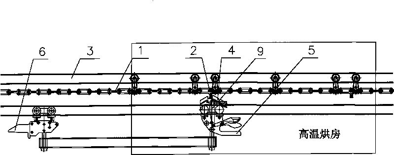
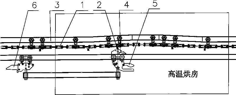
[0013] Such as figure 2 As shown, when the trolley 17 enters the drying room, since the traction rail 3 of the chain 1 is lifted, the chain 1 and the push head 2 are lifted for a certain distance along the traction rail 3 (the height is greater than the depth of the groove of the lifting claw 4) , the lifting claw 4 of the trolley is disengaged from the push head 2 of the chain 1, and the trolley I 7 stops running.

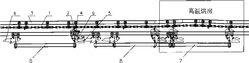
[0014] Such as image 3 Shown, the working process schematic diagram of the present invention:

[0015] After the stopped trolley I 7 dries in the drying room for a period of time, the stopper outside the drying room is opened, and the trolley II8 moves forward, and the trolley II 8 drives the trolley I 7 to move forward until the trolley II 8 runs to the rail lifting place . In the process of trolley II 8 pushing trolley I 7 to run, the front shovel 5 of trolley II 8 is inserted into the tail plate 6 of trolley I 7. Since the traction rail 3 is lifted for a c...


PUM


Abstract

The invention relates to a conveying device capable of stopping, which is used for high temperature drying rooms and comprises a chain and a chain traction rail, wherein pushing heads are distributed on the chain at intervals; and the part of the traction rail in a drying room is provided with a rail. In the invention, a mechanical structure principle is adopted, a stop is not needed to be arranged in the drying room, and a trolley can be automatically disconnected from the pushing heads of the chain in the drying room, thereby realizing stopping. The invention has the advantages of low cost, safety, reliability, maintenance free, and the like.

Description

technical field [0001] The invention relates to a mechanical conveying device, in particular to a conveying device that can be parked for a high-temperature drying room. Background technique [0002] In the high-temperature drying room, the trolley is generally conveyed by a chain. In the previous design concept, as long as there is a place to stop in the line, the stopper must be arranged, and the high-temperature drying room is no exception. Due to the particularity of the high-temperature drying room, there are many problems in arranging the stopper in the drying room. There are two ways to realize the stop: one way is to place the actuator of the stopper outside the drying room to avoid the effect of the high temperature on the actuator. Use the lever principle to realize internal parking; the other is to use a high temperature resistant cylinder. Arrange the stopper directly in the oven. The former method has complex structure and poor reliability, and the latter met...

Claims


Application Information

Patent Timeline
Patent Type & Authority Applications(China)
IPC IPC(8): F26B25/00B65G17/00B65G21/22B65G47/88
Inventor 薛浩然孙卫军
Owner 无锡市通达输送设备有限公司
Why Eureka
Try Eureka