Pneumatic valve locking plate dismounting device

A valve lock plate, pneumatic technology, applied in the direction of metal processing, metal processing equipment, manufacturing tools, etc., can solve the problems of reduced maintenance efficiency, inconvenient production, time-consuming and laborious, etc., to achieve precise operation, high work efficiency, and reduce compression The effect of air volume

Inactive Publication Date: 2010-04-21
周伟宏
View PDF0 Cites 10 Cited by
  • Summary
  • Abstract
  • Description
  • Claims
  • Application Information

AI Technical Summary

Problems solved by technology

[0002] In the prior art, many valve lock plate disassemblers are mostly of manual mechanical structure, using screw type or lever type, and there is no complete set of lock plate installation mechanism, and the valve spring upper seat together with the valve spring is first installed in the installation process. Compress, then place the valve lock pieces one by one in the valve lock piece slots, and then release the spring, which is time-consuming and laborious, which brings inconvenience to production and greatly reduces maintenance efficiency

Method used


Image

  • Pneumatic valve locking plate dismounting device
  • Pneumatic valve locking plate dismounting device
  • Pneumatic valve locking plate dismounting device

Examples


Embodiment 1

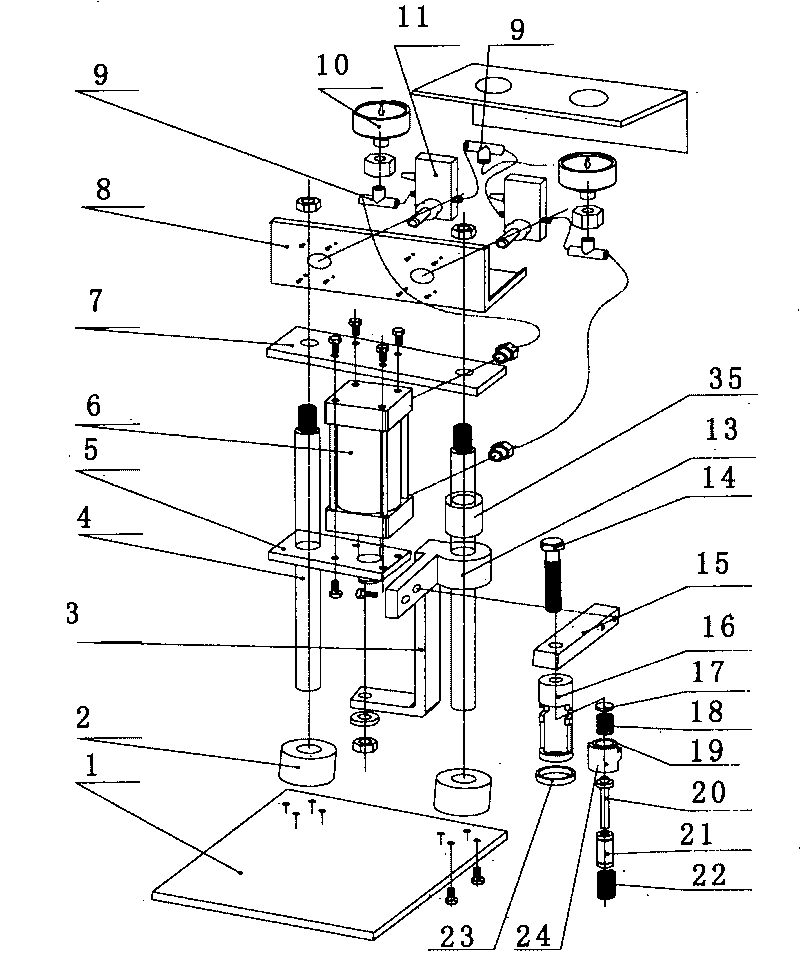
[0033] Such as figure 1 , Figure 4 , Figure 6 and Figure 8 A pneumatic valve lock plate remover with a bolt-type lock plate placer is shown, including a base plate 1, a column 4 fixed on the base plate, a column connecting block 2, a cylinder 6, a connecting rod 3, and a movable frame 13 1. Lock plate dismounting mechanism and valve head gasket, lock plate dismounting mechanism includes valve spring compressor 16, valve spring compressor force arm 15 and lock plate placer 26; The upper end of the cylinder 6 is fixed on the upper fixing plate 7, The lower end of the cylinder 6 is fixed on the lower fixed plate 5, the lower fixed plate 5 is movably socketed on a column 4, the piston of the cylinder 6 passes through the lower fixed plate 5 and the connecting rod 3 is fixedly connected to the other end of the connecting rod 3 and the movable frame 13 Fixedly connected, the movable frame 13 is movably socketed on another column 4 through a sliding sleeve 35, the valve spring ...

Embodiment 2

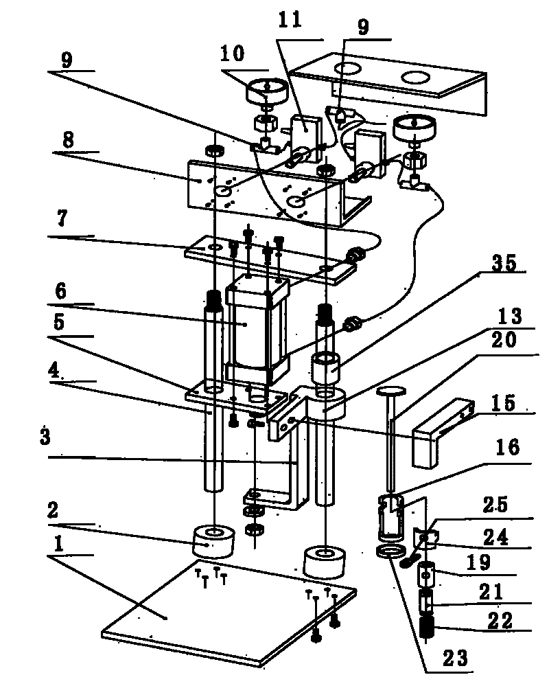
[0035] Such as figure 2 , Figure 5 , Figure 7 and Figure 8 A pneumatic valve lock plate remover with a fixed lock plate placer is shown, including a base plate 1, a column 4 fixed on the base plate, a column connecting block 2, a cylinder 6, a connecting rod 3, and a movable frame 13 1. Lock plate dismounting mechanism and valve head gasket. The lock plate dismounting mechanism includes valve spring compressor 16, valve spring compressor arm 15 and lock plate placer 26; the upper end of cylinder 6 is fixed on the upper fixing plate 7, and the cylinder 6 The lower end is fixed on the lower fixed plate 5, the lower fixed plate 5 is movably socketed on a column 4, the piston of the cylinder 6 passes through the lower fixed plate 5 and is fixedly connected with the connecting rod 3, and the other end of the connecting rod 3 is fixed with the movable frame 13 connection, the movable frame 13 is movably socketed on another column 4 through the sliding sleeve 35, the movable f...

Embodiment 3

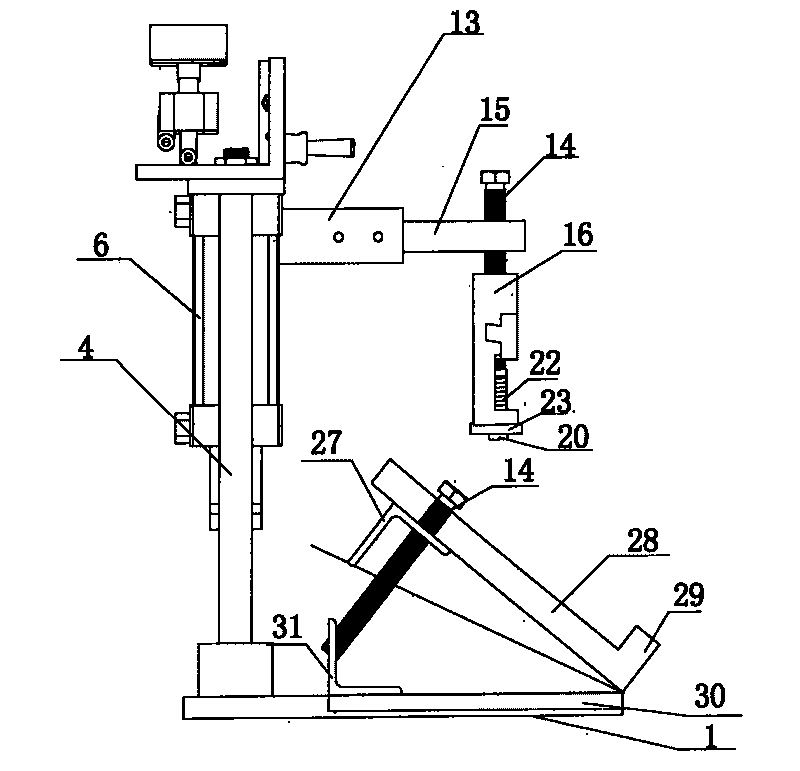
[0037] Such as image 3 and Figure 8 As shown, the pneumatic valve lock plate remover also includes a cylinder head angle adjustment bracket placed on the bottom plate 1, and the cylinder head angle adjustment bracket includes an upper adjustment plate 28, a lower adjustment plate 30, an upper support angle iron 27, a lower Support angle iron 31, one end of upper adjustment plate 28 is provided with baffle plate 29, the upper adjustment plate 28 and lower adjustment plate 30 are hinged at one end of baffle plate 29, and the upper support angle iron 27 is fixed on the lower side of the other end of upper adjustment plate 28 , the lower support angle iron 31 is fixed on the upper side of the opposite end of the hinged end of the lower adjustment plate 30, and the upper adjustment plate 28 is fixed on one end of the upper support angle iron 27 to be provided with 1-3 adjustment bolts 14; the valve head pad is placed On the upper adjustment plate 28 of the cylinder head angle ad...


PUM


Abstract

The invention relates to a pneumatic valve locking plate dismounting device, comprising a bottom plate, an upright post, an air cylinder, a connecting rod, a movable frame, a locking plate dismounting mechanism and a valve head pad. The locking plate dismounting mechanism comprises a valve spring compressor, an arm of force of the valve spring compressor and a locking plate placing device; the upright post is fixed on one side of the bottom plate, the air cylinder is fixed between an upper fixing plate and a lower fixing plate, the top of an air cylinder piston is fixedly connected with the connecting rod, the other end of the connecting rod is fixedly connected with the movable frame, the movable frame is connected with the other upright post in a sleeved manner, the arm of the valve spring compressor is fixed on the movable frame, the valve spring compressor is vertically connected with the arm of force of the valve spring compressor, the locking plate placing device is embedded in the valve spring compressor; two air valves with control handles are arranged on the side face of a shell of an air valve control box fixed on the fixing plate, a barometer is arranged between the joints of the air valve and the air cylinder; and the air valve head pad is arranged on the bottom plate. By adopting the invention, the locking plate of the cylinder cover can be mounted and dismounted with less time, less labor, precise operation and high efficiency.

Description

technical field [0001] The invention relates to a device for removing and installing an air valve locking plate, in particular to a pneumatic type removing and installing device for an air valve locking plate. Background technique [0002] In the prior art, many valve lock plate disassemblers are mostly of manual mechanical structure, using screw type or lever type, and there is no complete set of lock plate installation mechanism, and the valve spring upper seat together with the valve spring is first installed in the installation process. Compress, then place the valve lock pieces one by one in the valve lock piece slots, and then release the spring, which is time-consuming and laborious, which brings inconvenience to production and greatly reduces maintenance efficiency. Contents of the invention [0003] The object of the present invention is to provide a pneumatic valve lock plate dismantling device which saves time and labor and improves maintenance efficiency. [0...

Claims


Application Information

Patent Timeline
Patent Type & Authority Applications(China)
IPC IPC(8): B23P19/04B23P19/027
Inventor 周伟宏
Owner 周伟宏
Why Eureka
Try Eureka