Wind generating set

A technology for wind turbines and components, applied in the direction of wind turbines, engines, engine components, etc., can solve the time-consuming problem of main bearing installation, and achieve the effect of saving time and labor for installation and simplifying the structure

Active Publication Date: 2016-04-20
BEIJING GOLDWIND SCI & CREATION WINDPOWER EQUIP CO LTD
View PDF11 Cites 7 Cited by
  • Summary
  • Abstract
  • Description
  • Claims
  • Application Information

AI Technical Summary

Problems solved by technology

[0009] Embodiments of the present invention provide a wind power generating set to solve the problem of time-consuming installation of the main bearing of the existing wind generating set

Method used


Image

  • Wind generating set
  • Wind generating set
  • Wind generating set

Examples


Embodiment 1

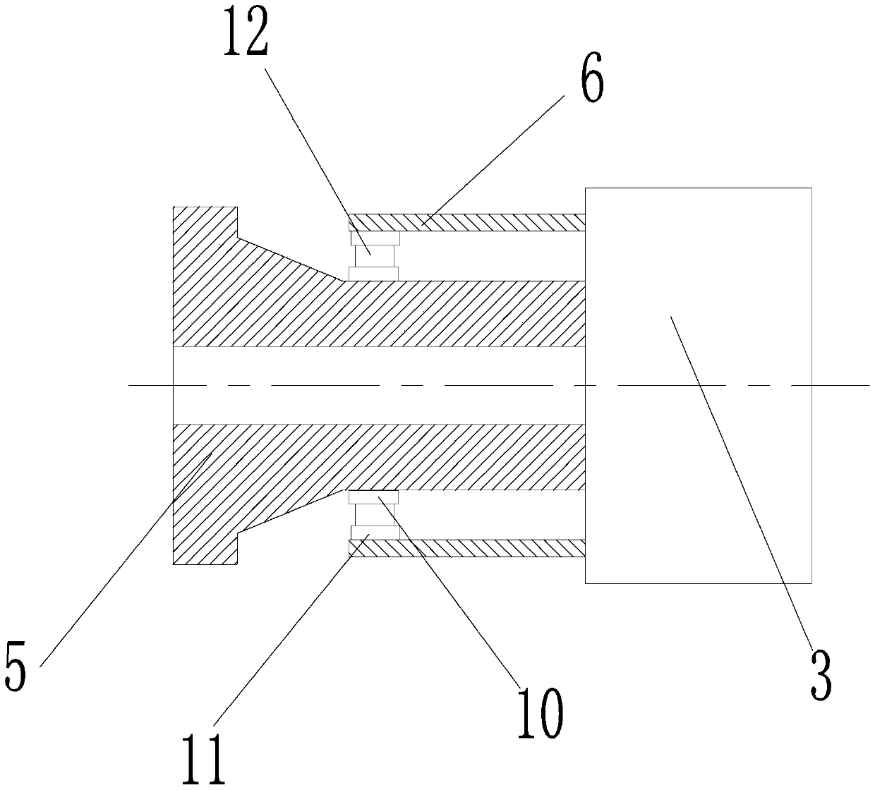
[0031] Such as Figure 5 As shown in the embodiment of the fundamental invention, the wind power generator includes an inner shaft 5 and an outer shaft 6 sleeved outside the inner shaft 5, and a bearing assembly is arranged between the inner shaft 5 and the outer shaft 6 to The inner shaft 5 and the outer shaft 6 can rotate relatively, and at the same time, they can transmit the gravity and wind load of the impeller 2. The bearing assembly includes an inner ring, an outer ring, and a rolling assembly 12 arranged between the inner ring and the outer ring. The inner ring is integrally formed on the inner shaft 5 and / or the outer ring is integrally formed It is formed on the outer shaft 6. This arrangement can solve the problem of easy axial movement of the inner ring and / or outer ring of the bearing during use, and ensure the reliability of the bearing during use. In addition, since the inner ring is integrally formed on the inner shaft 5 and the outer ring is integrally formed ...


PUM


Abstract

The invention relates to a wind generating set, comprising an inner shaft and an outer shaft sleeving the inner shaft; a bearing assembly is arranged between the inner shaft and the outer shaft; the bearing assembly comprises an inner ring, an outer ring and a rolling assembly arranged between the inner ring and the outer ring; the inner ring is integrally formed on the inner shaft and / or the outer ring is integrally formed on the outer shaft. The inner ring and / or outer ring in the bearing are / is respectively integrally formed in the inner shaft and / or outer shaft, the structure of a main bearing is simplified and the main bearing is more timesaving and laborsaving to mount.

Description

Technical field [0001] The invention relates to the field of wind power generation equipment, and in particular to a wind power generating set. Background technique [0002] The structure of wind generators can generally be divided into two categories: doubly-fed units with a speed increasing box arranged between the impeller 2 and the generator 4 ( figure 1 ) And direct drive units without gearbox 3 ( figure 2 ). [0003] Such as figure 1 As shown, in the doubly-fed unit, when the fan is working normally, the impeller 2 rotates to drive the low-speed main shaft to rotate, the low-speed shaft drives the high-speed shaft to rotate through the gearbox 3, and the high-speed shaft drives the rotor of the generator 4 to rotate to achieve wind energy to electric energy Conversion. Such as figure 2 As shown, in a direct-drive unit, when the fan is working normally, the impeller 2 rotates, and the rotor of the generator 4 is directly driven to rotate through the rotating shaft to realiz...

Claims


Application Information

Patent Timeline
Patent Type & Authority Applications(China)
IPC IPC(8): F03D80/70
CPCF16C3/023F16C33/581F16C2360/31
Inventor 彭云武青虎时洪奎
Owner BEIJING GOLDWIND SCI & CREATION WINDPOWER EQUIP CO LTD
Why Eureka
Try Eureka