Device for aligning concentricity and carrying out automatic welding during planted pile butt joint

An automatic welding, quasi-concentric technology, applied in welding equipment, auxiliary devices, auxiliary welding equipment, etc., can solve the problems of low efficiency, unsatisfactory all-round scheduling, labor-intensive and time-consuming, etc.

Active Publication Date: 2020-01-17
厦兴科技(浙江)有限公司
View PDF16 Cites 7 Cited by
  • Summary
  • Abstract
  • Description
  • Claims
  • Application Information

AI Technical Summary

Problems solved by technology

However, according to the inventor’s understanding, for the alignment of vertical piles or steel pipes to find the concentricity, it is still necessary to use a crane to hoist the piles or pipes to the joints and manually inspect and align them manually, which is time-consuming, laborious, inefficient and difficult to achieve. Concentricity
[0003] The welding of the seam is initially manual welding, and its welding quality and efficiency cannot be guaranteed
In recent years, automatic welding equipment running along the circular track has gradually appeared, but they all have the following shortcomings: 1. It is still laborious and time-consuming to manually install the circular guide rail and welding equipment on the joint of piles such as prefabricated pipe piles
2. Basically rely on rollers or pulleys to walk, there is slippage, and the controllability of its walking speed and precision is not high
3. The up, down, left and right angles of the welding torch can be adjusted in all directions, which is not ideal

Method used


Image

  • Device for aligning concentricity and carrying out automatic welding during planted pile butt joint
  • Device for aligning concentricity and carrying out automatic welding during planted pile butt joint
  • Device for aligning concentricity and carrying out automatic welding during planted pile butt joint

Examples


Embodiment Construction

[0029] The specific embodiments of the present invention will be further described below in conjunction with the accompanying drawings. What needs to be declared here is that the descriptions of these specific implementations are used to help understand the present invention, but are not intended to limit the present invention. In addition, the technical features involved in the various specific embodiments of the present invention described below may be combined with each other as long as they do not constitute conflicts with each other.

[0030] Such as figure 1 , figure 2 , image 3 , Figure 4 , Figure 5 , Figure 6 , Figure 7 , Figure 8 , Figure 9 , Figure 10 , Figure 11 shown

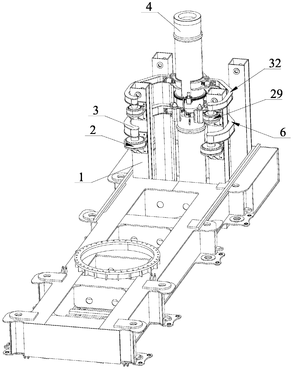
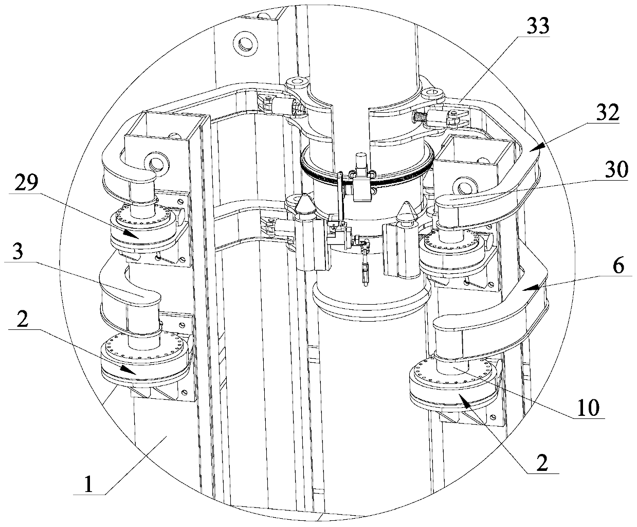
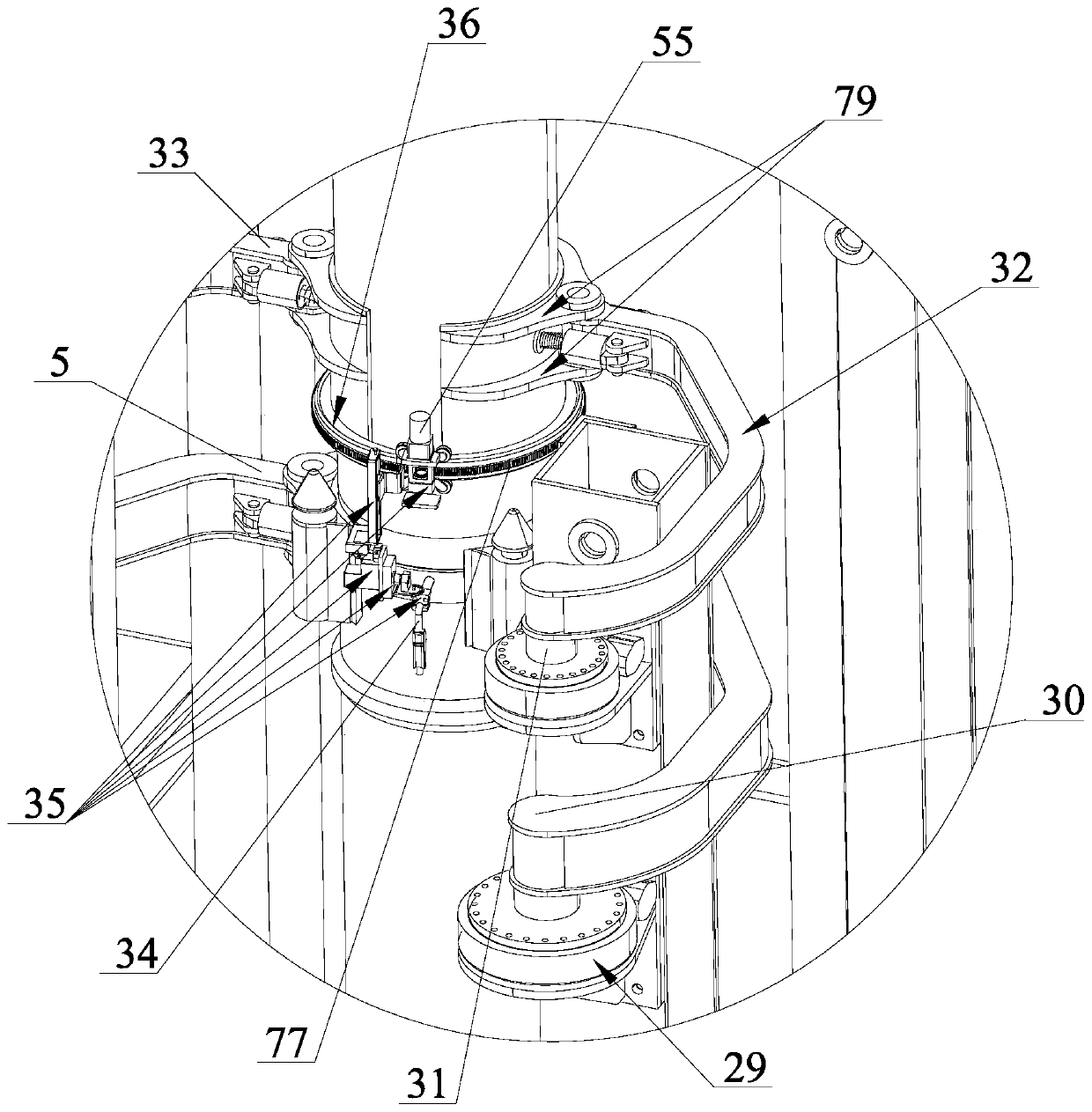
[0031] The device for aligning concentricity and automatic welding of pilings in the present invention includes a circular guide rail 36 , a welding torch frame 35 rotatably fitted on the circular guide rail 36 , and a welding torch 34 mounted on the welding torch frame 35 .

[...


PUM


Abstract

The invention discloses a device for aligning the concentricity and carrying out automatic welding during planted pile butt joint. The device comprises a round guide rail, a welding gun frame arrangedon the round guide rail in a running fit manner, and a welding gun mounted on the welding gun frame and further comprises a pair of first pile holding arms, a pair of second pile holding arms and tworotary motors mounted on a rack. The first pile holding arms and the second pile holding arms are symmetrically arranged and synchronously act. An output shaft of each rotary motor is fixed to the swing end of a respective swing arm, and respective supporting frames are hinged to the pile holding ends of the swing arms. Structures for allowing upper piles and lower piles to automatically align the concentricity when the upper piles fall off are arranged on the supporting frames. The pile holding ends of the swing arms are further connected with arc-shaped plates abutting against the butt joint positions of the upper pile and the lower piles through elastic devices. Semi-circular guide rails are fixed to the two arc-shaped plates, and after the two arc-shaped plates hold the piles, the twosemi-circular guide rails form a round guide rail. According to the device for aligning the concentricity and carrying out automatic welding during planted pile butt joint, the upper piles and the lower piles connected end to end can be automatically aligned, and the device can be automatically mounted at the butt joint positions of the piles.

Description

technical field [0001] The invention relates to the technical field of pile planting, in particular to a device for butt jointing of planting piles to find out the concentricity and automatically weld them. Background technique [0002] In the field of foundation construction technology, foundation piles such as prefabricated pipe piles or steel pipes (the soil in the pipes shall be taken out with a rotary excavator and then poured into the cast-in-place piles) are required to be implanted end to end into the soil in many occasions. For pipe piles, four 15-meter-long pipe piles need to be connected end to end. It is not difficult to understand that from the perspective of construction quality and mechanical properties, both the upper and lower piles are required to be vertical and concentric with each other before welding. However, according to the inventor’s understanding, for the alignment of vertical piles or steel pipes to find the concentricity, it is still necessary t...

Claims


Application Information

Patent Timeline
Patent Type & Authority Applications(China)
IPC IPC(8): B23K37/02B23K37/053B23K101/06
CPCB23K37/0211B23K37/0276B23K37/0533B23K2101/06
Inventor 尚贤菊
Owner 厦兴科技(浙江)有限公司
Why Eureka
Try Eureka