T-shaped burning beam

A technology for burning beams and beam bodies, which is applied to burners, lighting and heating equipment, etc., can solve problems such as increasing equipment investment and maintenance costs, easily burning out the burner port, and affecting normal production, saving equipment investment and maintenance. cost, improve product quality, reduce and avoid the effect of local over-burning or burning

Active Publication Date: 2010-04-21
SHIJIAZHUANG XINHUA IND FURNACE CO LTD
View PDF2 Cites 6 Cited by
  • Summary
  • Abstract
  • Description
  • Claims
  • Application Information

AI Technical Summary

Problems solved by technology

As a result, the flame is too close to the beam body during combustion, or the flame is trapped in the burner mouth and burns, which is easy to burn the burner mouth and the "T" head of the combustion beam, causing oil leakage and other failures, and is forced to stop for maintenance or replacement unplanned Burning beams will affect normal production and increase equipment investment and maintenance costs

Method used


Image

  • T-shaped burning beam
  • T-shaped burning beam
  • T-shaped burning beam

Examples


Embodiment 1

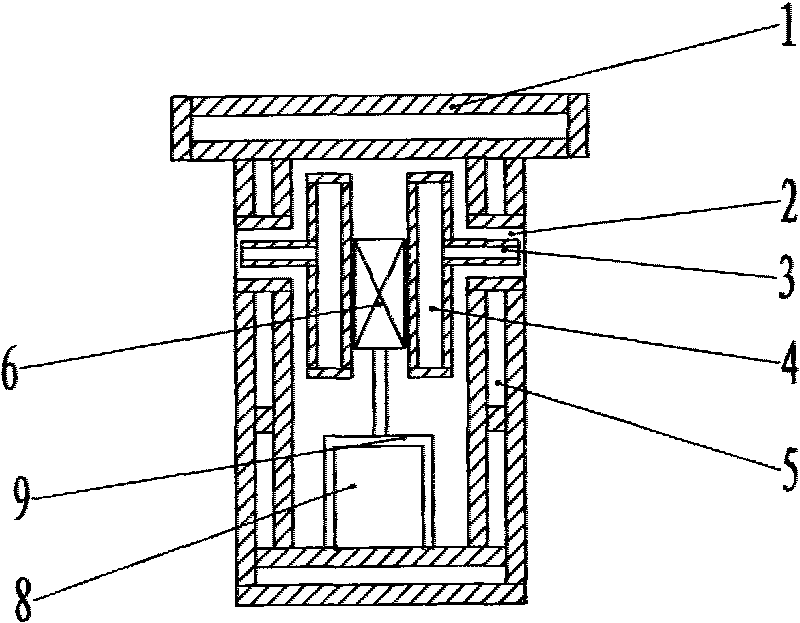
[0017] The "T"-shaped combustion beam of the present invention is composed of a beam body 1. The beam body is provided with a fuel pipeline 4 and an air passage 8. Both sides of the beam body are provided with burners 2, 10 burners on each side. A type of fuel nozzle 3 and an air outlet, the fuel nozzle 3 extends into the burner port, and the fuel pipeline is connected to the fuel nozzle. The air outlet is the gap around the fuel nozzle and communicates with the air passage. There are two fuel pipelines in the beam body, and the fuel pipelines are of rectangular box-like structure. The two fuel pipelines are fixedly installed in the air channel by fixing pieces 6, and the fixing pieces are supported by brackets 9. Each fuel pipeline is connected to the air passage. The fuel nozzle of the same side burner, the fuel nozzle is inserted into the burner port. Between the inner wall and the outer wall of the combustion beam, there is a cavity 5 through which a cooling medium circul...

Embodiment 2

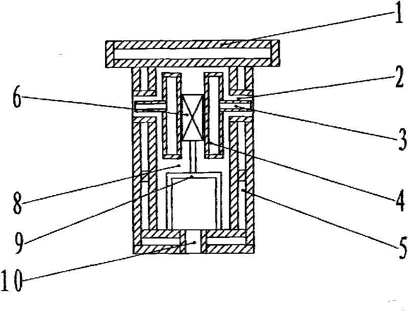
[0020] Another solution of the present invention is as figure 2 As shown, the lower part of the beam body is provided with 10 air nozzles 10 , and the air passages are connected to the air outlet of the burner 2 and the air nozzles 10 . The two fuel pipelines are fixedly installed in the air passage with fixing pieces 6 , and the fixing pieces are supported by brackets 9 . Other structures are the same as those of Embodiment 1.

[0021] The supplementary combustion-supporting air ejected from the air nozzles 10 at the lower part of the combustion beam disperses and flows upward under the suction action of the upper suction beam in the kiln body, and continues to burn with the incompletely burned fuel. In order to reduce the intensity of fuel combustion at the burner outlet and improve the uniformity of calcined products.

Embodiment 3

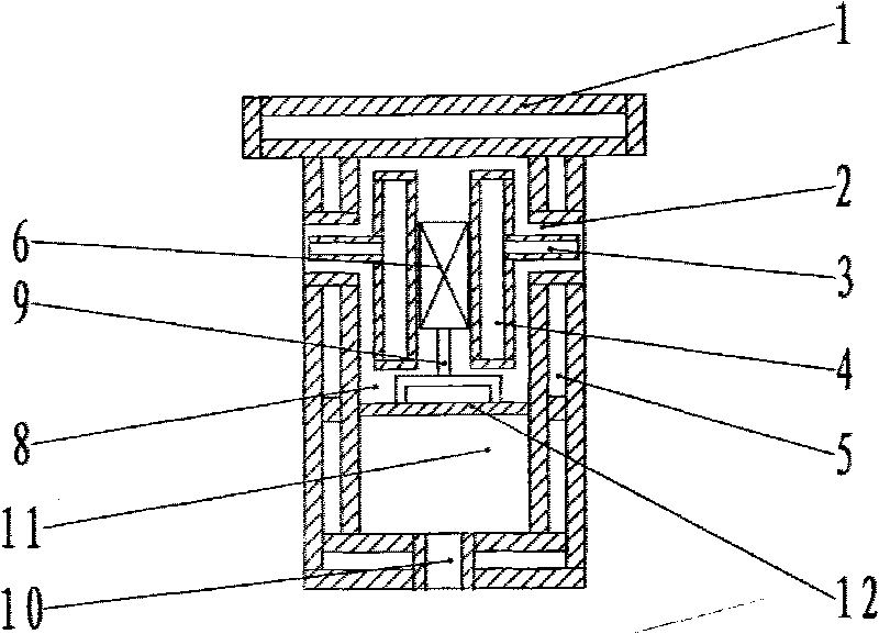
[0023] Another embodiment of the present invention is as follows image 3 As shown, the lower part of the beam body is provided with 10 air nozzles 10 , and the beam body is divided into upper and lower air passages 8 and 11 by a partition 12 . The fuel line 4 passes through the upper air passage 8 and communicates with the air outlet of the burner, and the lower air passage 11 communicates with the air nozzle 10 . Other structures are the same as those of Embodiment 1.

[0024] The supplementary combustion-supporting air ejected from the air nozzles 10 at the lower part of the combustion beam disperses and flows upward under the suction action of the upper suction beam in the kiln body, and continues to burn with the incompletely burned fuel. The pressure entering the upper air passage 8 is controlled to be lower than the pressure of the lower air passage 11, so that the amount of air ejected from the burner is lower than the theoretical value required for combustion, and th...


PUM


Abstract

The invention provides a T-shaped burning beam, which consists of a beam body. Fuel pipelines and an air channel are arranged in the beam body; two sides of the beam body are provided with burner nozzles, and each side comprises 5 to 20 burner nozzles; each burner nozzle comprises a lengthened fuel nozzle and an air outlet; and the air outlet is a gap around the fuel nozzle. Two fuel pipelines are fixedly arranged in the air channel by fixing elements, and each fuel pipeline is connected with the burner nozzles on the same side. The two fuel pipelines are arranged respectively; and the fuel nozzles are lengthened fuel nozzles and are inserted in burner nozzle mouths so that the fuel is burnt outside the burner nozzles, the flame is far away from the beam body wall, the burner nozzle mouths and a T-shaped head of the burning beam are prevented from being burnt out, the equipment investment and the maintenance cost are saved, and the service life of the burning beam is prolonged.

Description

technical field [0001] The invention belongs to the technical field of combustion equipment, and in particular relates to a T"-shaped combustion beam for furnaces and kilns Background technique [0002] Burning limestone in beam-type lime kiln is a new technology of lime production. The beam-type lime kiln has the advantages of low energy consumption, good lime product quality, strong production capacity, and large operation flexibility, and is widely used in the production of lime for metallurgy, chemical industry and other purposes. The combustion beam is the core equipment of the beam lime kiln. The beam body of the combustion beam is provided with burners, fuel pipelines and combustion-supporting air pipelines. The fuel pipelines and combustion-supporting air pipelines deliver fuel and combustion-supporting air to the burners. to burn. The applicant's patent application number is 200320111077.3, and the utility model patent titled "Internal and External Heating Lime Fu...

Claims


Application Information

Patent Timeline
Patent Type & Authority Applications(China)
IPC IPC(8): F23D11/00F23D11/36F23D11/38C04B2/10
Inventor 贾会平
Owner SHIJIAZHUANG XINHUA IND FURNACE CO LTD
Why Eureka
Try Eureka