
Constant-voltage electric brush device of motor

A piezoelectric and brush technology, used in electromechanical devices, electrical components, etc., can solve problems such as reduced pressure on brush collector rings, wear of brushes and collector rings, and poor contact.

Inactive Publication Date: 2010-04-21
WUXI NEW GREAT POWER ELECTRICAL MACHINE
View PDF3 Cites 2 Cited by
  • Summary
  • Abstract
  • Description
  • Claims
  • Application Information

AI Technical Summary

Problems solved by technology

[0005] The purpose of the present invention is to provide a constant voltage brush device for a motor, which can solve the problem of wear caused by friction between the conventional brushes and collector rings, which in turn causes pressure reduction between the brush collector rings. bad contact problem

Method used


Image

  • Constant-voltage electric brush device of motor
  • Constant-voltage electric brush device of motor
  • Constant-voltage electric brush device of motor

Examples


Embodiment Construction

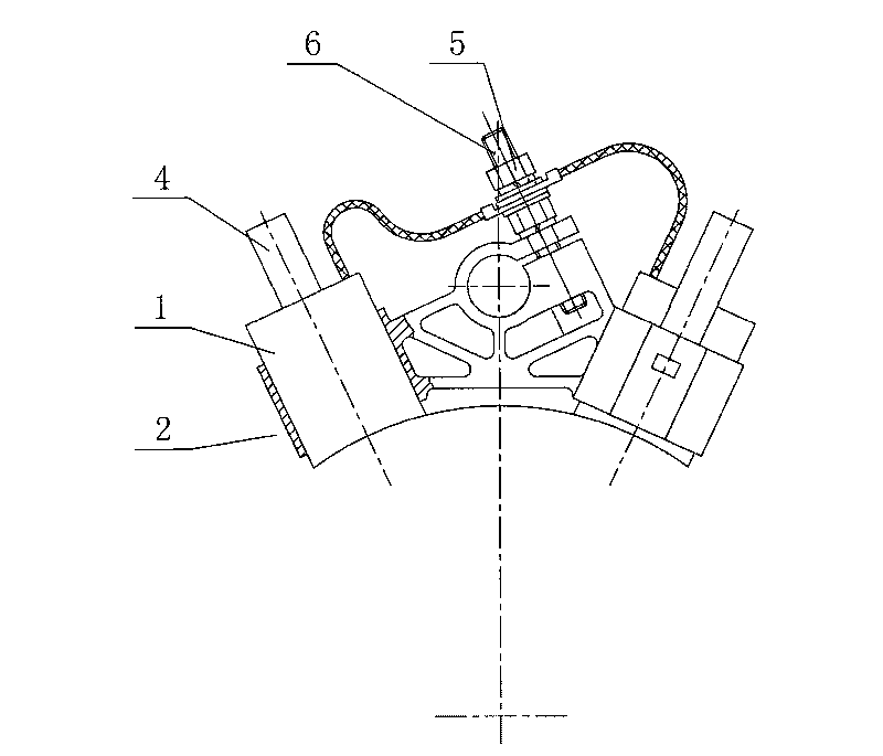
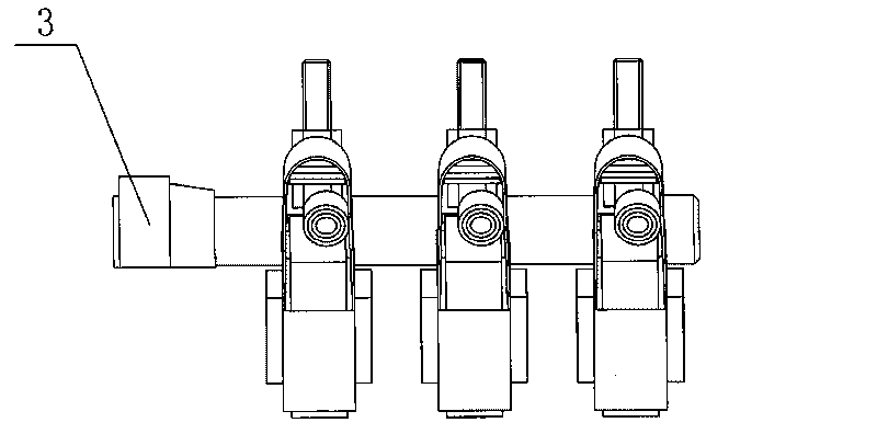
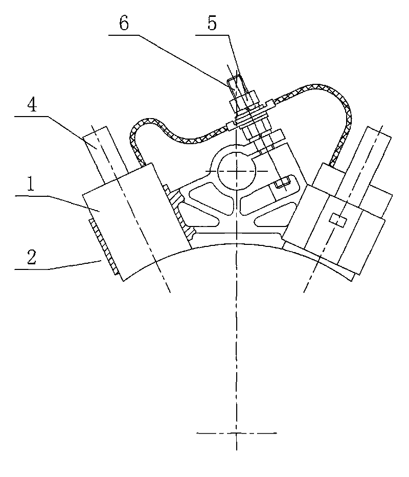
[0014] Such as Figure 1-2 As shown, the constant voltage brush device of the motor according to the present invention includes a brush box 2, a brush 1 installed inside the brush box 2, a brush bar 3 passing through the brush box 2, and the brush box 2 is fixed on the brush bar 3 and tightened by the nut 5 and the set screw 6, a constant pressure spring 4 is installed at the rear of the brush 1, and the constant pressure spring 4 is a rigid spring.

[0015] The constant pressure spring 4 can support the contact between the brush 1 and the collector ring, and since the constant pressure spring 4 is a rigid spring, the radius of curvature and the number of turns of the constant pressure spring can meet the rigidity requirements, especially after the brush is worn out, the electric The brush produces a small axial displacement, and the pressure of the constant pressure spring will only change slightly at this time, but the pressure is still within the allowable pressure control ...


PUM


Abstract

The invention relates to a constant-voltage electric brush device of a motor, comprising a brush box, an electric brush mounted inside the brush box and a brush rod penetrating through the brush box. The brush box is fixed on the brush rod and screwed by nuts and tightening bolts; a constant-voltage spring which is a rigid spring is mounted at the rear part of the electric brush and can support the electric brush to get in contact with a collecting ring; since the constant-voltage spring is rigid, the curvature radius and the number of circles of the constant-voltage spring both can meet the requirement on rigidity, and especially when abrasion is generated, the electric brush generates tiny axial displacement, the pressure of the constant-voltage spring only changes slightly, but the pressure is still in an allowed pressure control range without causing poor contact between the electric brush and the collecting ring. Therefore, the electric brush and the collecting ring are in tight contact all the time to ensure the favorable operation of the motor.

Description

technical field [0001] The invention relates to a three-phase asynchronous motor, in particular to a brush device on the motor. Background technique [0002] During the operation of the motor, the brush and the collector ring are always in contact. With the increase of the running time, the brush will gradually wear out, and the pressure of the spring that tightens the brush will decrease accordingly, resulting in Poor contact between brushes and slip rings. [0003] Therefore, based on the above-mentioned problems, the problem solved by this patent is how to ensure that the pressing force between the brush and the collector ring remains unchanged even if the brush is worn after running for a certain period of time. . In this way, if it can be ensured that the pressure between the brush and the collector ring remains constant or the fluctuation range of the change is small (within the range allowed by stable contact), then it will be possible to avoid damage to the brush a...

Claims


Application Information

Patent Timeline
IPC IPC(8): H02K13/00
Inventor 赵卫国
Owner WUXI NEW GREAT POWER ELECTRICAL MACHINE
Learn More