
Cooling fan for traction transformer system of motor train unit train

A traction transformer and cooling fan technology, applied in transformer/inductor cooling, machine/engine, liquid fuel engine, etc., can solve the problem of less wind power, unsatisfactory heat dissipation effect of EMU train traction transformer system, and difficult to adapt to cooling and heat dissipation requirements and other problems, to achieve the effect of large wind force, compact structure and weight reduction

Inactive Publication Date: 2010-04-28
HUNAN TYEN MACHINERY
View PDF0 Cites 9 Cited by
  • Summary
  • Abstract
  • Description
  • Claims
  • Application Information

AI Technical Summary

Problems solved by technology

[0003] At present, the cooling fan of the traction transformer system of the EMU mainly adopts the structure of "moving impeller + rear deflector impeller" (R+S level) or "front deflector impeller + movable impeller" (P+R level). The fan with this structure has only one moving impeller, resulting in less wind power, and its heat dissipation effect on the traction transformer system of the EMU train is not ideal, and it is difficult to meet the cooling and heat dissipation requirements of the traction transformer system of the EMU train with a speed of more than 300 kilometers per hour

Method used


Image

  • Cooling fan for traction transformer system of motor train unit train
  • Cooling fan for traction transformer system of motor train unit train
  • Cooling fan for traction transformer system of motor train unit train

Examples


Embodiment 1

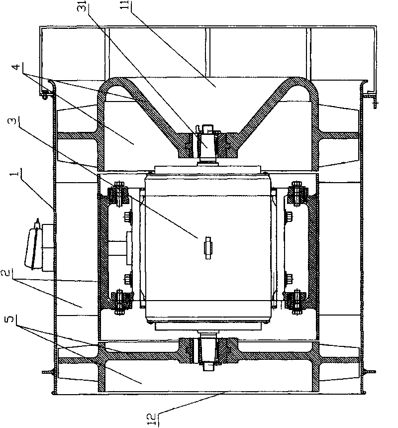
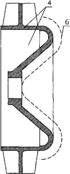
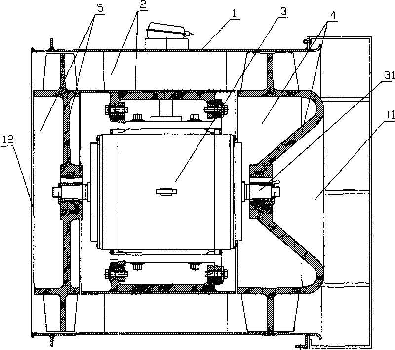
[0019] A cooling fan for the traction transformer system of an EMU train, which includes a fan housing 1, a guide wind impeller 2, a motor 3, an air inlet moving impeller 4 and an air outlet moving impeller 5; the guide wind impeller 2 is fixedly installed in the fan housing 1, the motor 3 is a motor with a double shaft extension structure, that is, the rotating output shaft 31 of the motor 3 stretches out from both ends of the motor body, and the motor 3 is installed in the hub of the guide wind impeller 2; the moving impeller 4 of the air inlet is installed on One end of the rotating output shaft 31 of the motor 3 near the air inlet 11 is located in the fan casing 1; Inside, the direction of the blades of the moving impeller 4 at the air inlet and the moving impeller 5 at the air outlet are in the same direction, that is, when the motor 3 rotates, the air supply direction of the moving impeller 4 at the air inlet and the moving impeller 5 at the air outlet are both to send ai...


PUM

PropertyMeasurementUnit
Diameteraaaaaaaaaa

Abstract

The invention relates to a cooling fan for a traction transformer system of a motor train unit train, which comprises a fan shell (1), a flow guidance fan impeller (2), a motor (3), an air inlet impeller (4) and an air outlet impeller (5), wherein the flow guidance fan impeller (2) is fixedly arranged in the fan shell (1); the motor (3) is arranged in a hub of the flow guidance fan impeller (2); a rotating output shaft (31) of the motor (3) extends out of two ends of the motor body; the air inlet impeller (4) is arranged at one end, close to an air inlet (11), of the rotating output shaft (31) of the motor (3) and is positioned in the fan shell (1); and the air outlet impeller (5) is arranged at the other end, close to an air outlet (12), of the rotating output shaft (31) of the motor (3) and is positioned in the fan shell (1). The cooling fan is characterized by enough wind power and small size, and is particularly suitable for cooling and radiating the traction transformer system of the motor train unit train with the speed of over 300 kilometers per hour.

Description

technical field [0001] The invention relates to a fan for cooling the traction transformer system of a high-speed electric locomotive. Specifically, the air volume generated by the fan passes through the radiator in the traction transformer system at a certain pressure to take away the heat generated during the operation of the traction transformer of the locomotive. , to ensure the heat load level of the entire high-speed electric locomotive traction transformer system, especially a cooling fan for the traction transformer system of an EMU train. Background technique [0002] According to the national railway development strategy, the country invested heavily in the high-speed railway network, and introduced and produced 200km / h EMU locomotives. With the acceleration of the national high-speed railway construction, the country vigorously advocates the introduction, digestion, absorption and re-innovation. On the basis of the 200-kilometer EMU locomotive, it vigorously indep...

Claims


Application Information

Patent Timeline
IPC IPC(8): F04D25/08F04D29/32F04D29/38F04D29/52F04D29/02H01F27/08
Inventor 王一棣吴建成刘立明陈文唐灵芝
Owner HUNAN TYEN MACHINERY
Learn More