A main current-carrying contact system

A contact system and current-carrying technology, applied in transformers, electrical components, variable inductors, etc., can solve the problem that the tap changer cannot be applied, and achieve the effect of simple structure, reasonable spacing and reliable operation.

Active Publication Date: 2011-12-21
贵州长征电气有限公司
View PDF0 Cites 0 Cited by
  • Summary
  • Abstract
  • Description
  • Claims
  • Application Information

AI Technical Summary

Problems solved by technology

[0003] The existing technology with a rotation angle of less than 80 degrees is only suitable for on-load tap-changers for transformer oil arc extinguishing, but it cannot be applied to some tap-changers with larger rotation angles of 100-120 degrees.

Method used


Image

  • A main current-carrying contact system
  • A main current-carrying contact system
  • A main current-carrying contact system

Examples


Embodiment Construction

[0035] The invention utilizes a simple structure, which can match the program requirements of the on-load tap changer and operate in a relatively large range. During the operation, under the premise of satisfying the preset overtravel, the angle of disengagement and closing is relatively small. The opening distance in the middle process of disengaging and closing is reasonable, and at the same time, the locking circle structure effectively guarantees the reliable operation of the mechanism.

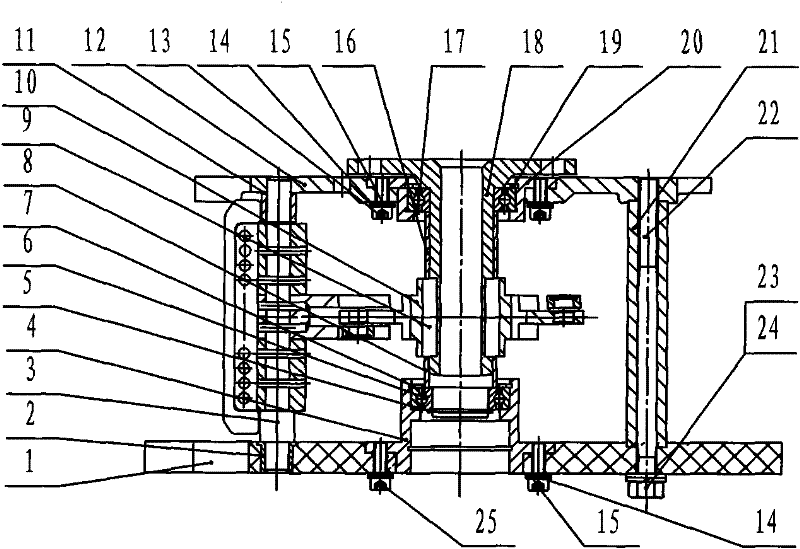
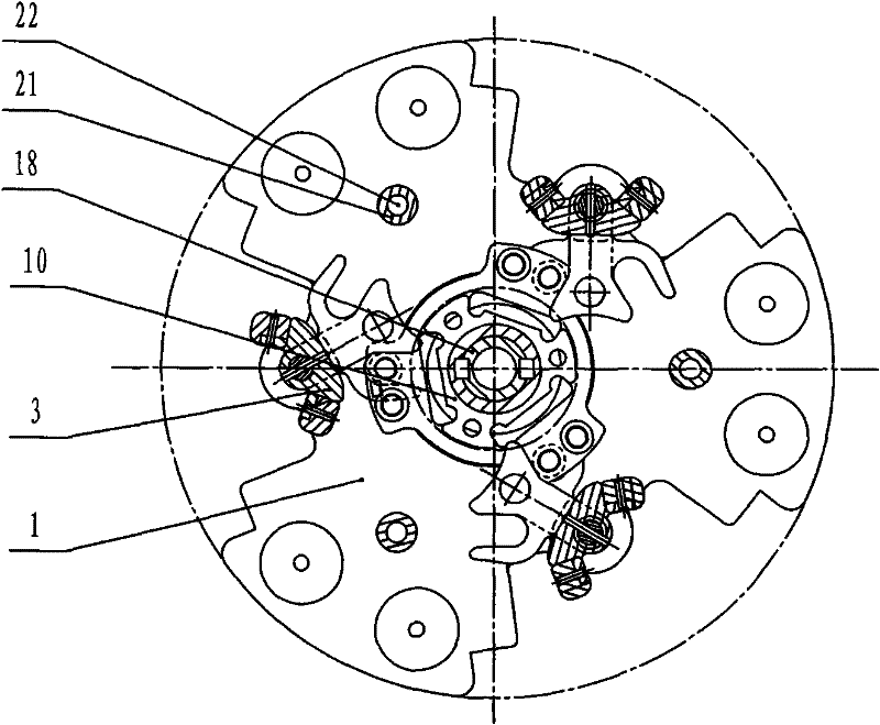
[0036] figure 1 and figure 2 It is a front view and a cross-sectional view of the main current-carrying contact system of the present invention. As shown in the figure, the main current-carrying contact system of the present invention includes: an upper mounting plate 12, a lower mounting plate 1, a first bearing bracket 4, and a second bearing bracket 20. The first bearing 6 , the second bearing 17 , the rotating shaft 18 and the first liner 21 .

[0037] The lower mounting plate 1 is...


PUM


Abstract

The invention discloses a main current-carrying contact system, comprising: an upper mounting plate; a lower mounting plate connected to the upper mounting plate through a first liner; a first bearing bracket fixed on the lower mounting plate , the first bearing bracket has a first bearing; the second bearing bracket is fixed on the upper mounting plate, and the second bearing bracket has a second bearing; the rotating shaft is connected with the first bearing and the second The bearing is connected; the driving disc is connected with the rotating shaft through a key; the main contact is connected with the driving disc. The structure of the main current-carrying contact system of the present invention is simple, and it can cooperate with the program requirements of the on-load tap changer to operate in a relatively large range. The rotation angle is small, and the opening distance in the middle process of disengaging and closing is reasonable. At the same time, the locking circle structure effectively guarantees the reliable operation of the mechanism.

Description

technical field [0001] The invention relates to a main current-carrying contact system, in particular to a main current-carrying contact system with a large rotation angle of a tap changer. Background technique [0002] The existing main current-carrying contact system with on-load tap changer is divided into a moving part and a current-carrying part. The rotation angle of the moving part depends on the rotation angle of the fast mechanism, usually within the range of 80 degrees; while the current-carrying part relies on the button contact The head and the static contact of the oil chamber are in contact with the current-carrying. There is a horn contact inside to connect the button contact with the neutral point. Single or even numbers of current-carrying contacts and neutral point contacts simultaneously contact the current-carrying structure. [0003] The structure of the rotation angle within 80 degrees in the prior art is only applicable to the on-load tap-changer for ...

Claims


Application Information

Patent Timeline
Patent Type & Authority Patents(China)
IPC IPC(8): H01H1/56H01F29/04
Inventor 吴选霞陶波杨波宋涛谭永禄潘凯秀王述波
Owner 贵州长征电气有限公司
Why Eureka
Try Eureka