
Super magnetostrictive high-speed jet valve

A giant magnetostrictive, high-speed injection technology, applied in valve details, valve devices, valve operation/release devices, etc., can solve the problems of high temperature, low driving efficiency, and complex structure of giant magnetostrictive rods. The effect of miniaturization, high drive efficiency and simple system structure

Active Publication Date: 2010-05-05
HARBIN INST OF TECH
View PDF0 Cites 6 Cited by
  • Summary
  • Abstract
  • Description
  • Claims
  • Application Information

AI Technical Summary

Problems solved by technology

[0003] The purpose of the present invention is to provide a supermagnetic Telescopic high-speed injection valve

Method used


Image

  • Super magnetostrictive high-speed jet valve
  • Super magnetostrictive high-speed jet valve
  • Super magnetostrictive high-speed jet valve

Examples


specific Embodiment approach 1

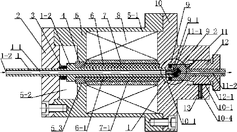
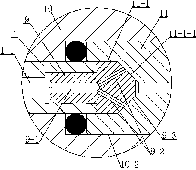
[0008] Specific implementation mode one: combine figure 1 and figure 2 Describe this embodiment, this embodiment includes the first push rod 1, the first input end cover 2, the first disc spring 3, the first top block 4, the first shell 5, the first giant magnetostrictive rod 6, the first A skeleton 7, a first coil 8, a plug 9, a first output end cover 10, a first valve seat 11 and a first adjustment seat 12, and a first magnetic field cavity 5- 1. The first disc spring cavity 5-2 is provided on the input end surface of the first housing 5, the first housing center hole 5-3 is provided at the axis of the first housing 5, and the first top block 4 is set on the first In the center hole 5-3 of the casing, a first stepped hole is provided at the axis of the first output end cover 10, and the first stepped hole is respectively the first installation hole 10-1 and the second installation hole from the output end to the input end. 10-2 and the third installation hole 10-3, the fi...

specific Embodiment approach 2

[0010] Specific implementation mode two: combination figure 1 To describe this embodiment, the material of the first ejector pin 1 of this embodiment is 1Cr18Ni9Ti or Monel400, and the material of the first skeleton 7 is PEEK. 1Cr18Ni9Ti and Monel400 materials are non-magnetic, corrosion-resistant and have high mechanical strength. The first ejector rod 1 serves as an output and fluid flow path while improving the magnetic circuit so that the magnetic field lines mainly pass through the first giant magnetostrictive rod 6. The PEEK material is non-conductive. It has good magnetic and heat insulation properties, and can be precisely processed and shaped to meet the matching gap with the first giant magnetostrictive rod 6, and play the role of heat insulation, fixing and protecting materials. Other components and connections are the same as those in the first embodiment.

specific Embodiment approach 3

[0011] Specific implementation mode three: combination figure 1 To describe this embodiment, the materials of the first jack block 4 , the first housing 5 and the first output end cover 10 in this embodiment are all made of No. 10 steel. No. 10 steel is a magnetic material, so that the first top block 4, the first shell 5, the first output end cover 10 and the first giant magnetostrictive rod 6 form a closed magnetic circuit, and the first giant magnetostrictive rod is added. 6 central magnetic field strength. Other components and connections are the same as those in the first embodiment.


PUM


Abstract

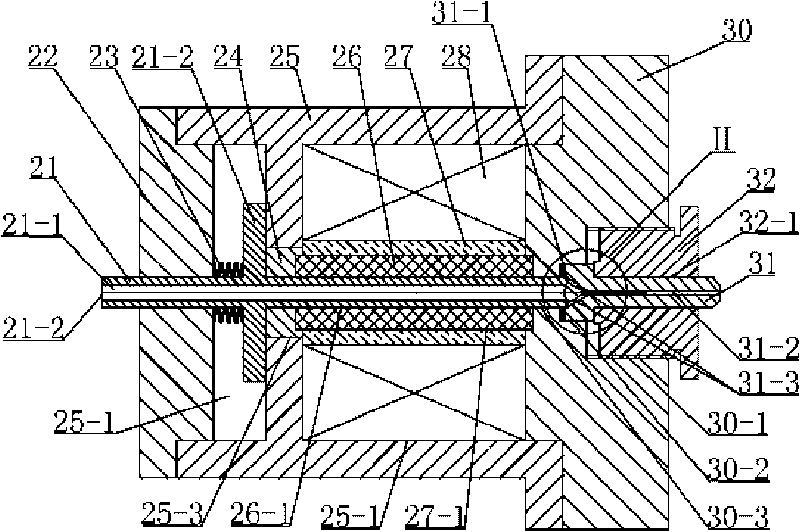
The invention relates to a high-speed jet valve, particularly to a super magnetostrictive high-speed jet valve for solving the problems of high temperature, complicated structure and larger volume existing in an actuator in a traditional super magnetostrictive valve and inhibiting super magnetostrictive rods. Scheme 1: a first coil is electrified to enable a first super magnetostrictive rod to stretch along an axis direction, a first jacking block drives a valve core to move, and a fluid flows through a first through hole, a plug central hole and a first inclined hole and flows out from a liquid circulation hole; the first coil is powered off, the first super magnetostrictive rod returns to the original length, and the valve core resets and keeps a normally closed working condition. Scheme 2: a second coil is electrified to enable a second super magnetostrictive rod to stretch along the axis direction, a second jacking block drives a second push rod to move, and the fluid flows through a second through hole and a second inclined hole and flows out from a valve seat central hole; the second coil is powered off, the second super magnetostrictive rod returns to the original length, and the second push rod resets and keeps the normally closed working condition. The super magnetostrictive high-speed jet valve is suitable for being used in high-precision flow control devices.

Description

technical field [0001] The invention relates to a high-speed injection valve. Background technique [0002] Most of the injection drives in existing high-speed injection valves use electromagnet actuators as converters between electricity and mechanical energy; the disadvantages of this drive method are: slow response speed (5-10ms), low control accuracy, and complex structure , The overall structure is large in size and cannot meet the needs of today's high-speed and high-precision electro-hydraulic control systems. To improve the performance of the electro-hydraulic control system, the bandwidth and response speed of its electro-mechanical converter must be improved. With the development of advanced manufacturing technology and microelectronics technology, the research and development of converters based on new functional materials has made the emergence and application of high-frequency response electro-mechanical converters a reality. At present, most of the research o...

Claims


Application Information

Patent Timeline
Patent Type & Authority Applications(China)
IPC IPC(8): F16K31/06
Inventor 李立毅张成明严柏平
Owner HARBIN INST OF TECH
Learn More