
High-efficiency and energy-saving filature collecting tank

A high-efficiency, energy-saving, collecting tank technology, applied in the direction of silk reeling, can solve the problems of time-consuming and laborious, incomplete collection, etc., and achieve the effect of complete collection and simple structure

Inactive Publication Date: 2010-05-12
HANGZHOU TIANFENG TEXTILE MACHINERY
View PDF1 Cites 1 Cited by
  • Summary
  • Abstract
  • Description
  • Claims
  • Application Information

AI Technical Summary

Problems solved by technology

[0003] The technical problem to be solved by the present invention is to provide a high-efficiency energy-saving silk reeling collection tank, which mainly solves the problem that the silk reeling machine's silk reeling tank and collection tank are set separately in the prior art, and there is no thread cocoon in the silk reeling tank. Or the pupal lining needs to be transported to the collection tank by the cocoon removal device for collection, which is time-consuming and laborious, and the collection is relatively incomplete and other technical problems

Method used


Image

  • High-efficiency and energy-saving filature collecting tank
  • High-efficiency and energy-saving filature collecting tank

Examples


Embodiment

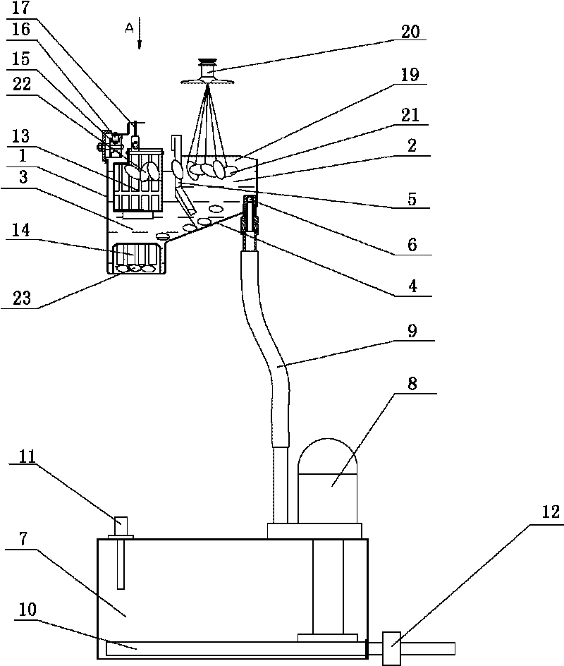
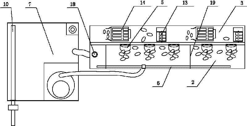
[0019] Embodiment: the high-efficiency energy-saving silk reeling collection tank of this example, as figure 1 , figure 2 , a frame 1 is arranged, and the frame is provided with a silk reeling tank 2 and a collection tank 3 arranged in parallel, the silk reeling tank and the collection tank are connected as a whole, and the bottom of the silk reeling tank 2 communicates with the collection tank through a swash plate 4. Between the silk reeling tank 2 and the collecting tank 3, a cocoon board 5 is provided, and the cocoon board is provided with one piece for each thread. The passage that thread cocoon 22 passes, and leave the gap that allows pupa liner 23 to pass through at the bottom of the cocoon plate and the silk reeling groove. The silk reeling tank 2 is internally connected with 40 small fences 19 to cut off the silk reeling groove, and 3 cocoon boards 5 are arranged between adjacent small fences. The collection tank 3 is provided with a floating cocoon catcher 13 and ...


PUM


Abstract

The invention relates to an automatic filature machine, in particular to a high-efficiency and energy-saving filature collecting tank. The invention mainly solves the technical problems that a filature tank and a collecting tank of the filature machine are arranged in a separate mode, cocoons without ends or tetelettes in the filature tank needs a cocoon shifting device to be delivered to the collecting tank for collection, so that the time and labor are wasted, the collection is incomplete, and the like in the prior art. The high-efficiency and energy-saving filature collecting tank comprises a stand, wherein the filature tank and the collecting tank are arranged on the stand; the filature tank and the collecting tank are arranged in a parallel mode and are connected into a whole; the collecting tank is communicated with the bottom of the filature tank through a sloping plate; 2 or more bar cocoon plates are arranged between the filature tank and the collecting tank; a channel which can allow the cocoons without ends to go through is left between adjacent bar cocoon plates, and clearances which can allow the tetelettes to go through are left at the lower end of the bar cocoon plates and the bottom of the filature tank; a drip catcher is arranged in the collecting tank and is connected with a drive device; and a water adding pipe is arranged at one side of the filature tank, is provided with a water spout hole, and is connected with a water delivering device.

Description

technical field [0001] The invention relates to an automatic silk reeling machine, in particular to an improvement on structures such as high-efficiency and energy-saving silk reeling collection tanks. Background technique [0002] During the silk reeling production process of the automatic silk reeling machine, the cocoon silk of the cocoon will not be reeled at one time, and the thread will definitely fall off in the middle of the reeling. The unthreaded cocoons in the reeling trough and the pupal linings that have been reeled after several times of reeling are taken out by the catcher and sent to the separator. The Chinese patent discloses an automatic silk reeling machine for double palace silk and a double palace silk cable reeling pot (authorized announcement number: CN 201305660Y), which includes a plurality of cable reeling pots arranged in two rows and facing each other. The pots are respectively arranged on both sides of the automatic silk reeling machine; the aut...

Claims


Application Information

Patent Timeline
Patent Type & Authority Applications(China)
IPC IPC(8): D01B7/04
Inventor 俞炳朱嫦丽俞江乔朱春阳马正楷俞先锋
Owner HANGZHOU TIANFENG TEXTILE MACHINERY
Learn More