
Integrated combined terminal row

A terminal block and integrated technology, applied in the direction of measuring devices, instruments, electrical components, etc., can solve the problems of unfavorable service life and reliability of electric energy meters, unguaranteed installation quality, time-consuming installation of electric energy meters, etc. The process is simple and fast, the overall cost is reduced, and the effect of reducing heat generation

Inactive Publication Date: 2010-05-12
WASION GROUP HLDG
View PDF0 Cites 5 Cited by
  • Summary
  • Abstract
  • Description
  • Claims
  • Application Information

AI Technical Summary

Problems solved by technology

The installation of electric energy meters with this structure is very time-consuming, and the installation quality cannot be guaranteed. Moreover, due to the large number of electrical connection points and large heat generation, it is very unfavorable to the service life and reliability of the electric energy meter, resulting in an increase in the overall cost.

Method used


Image

  • Integrated combined terminal row
  • Integrated combined terminal row
  • Integrated combined terminal row

Examples


Embodiment Construction

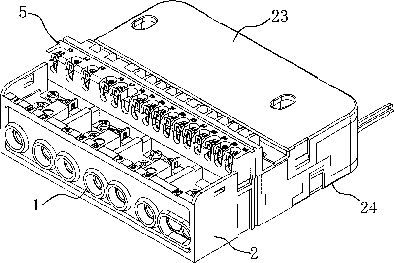
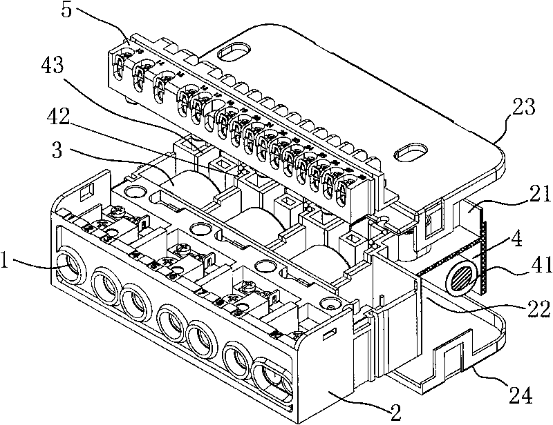
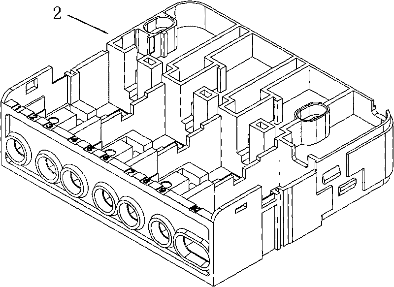
[0014] from Figure 1 to Figure 3 It can be seen that the integrated combined terminal block of the present invention still has a strong electric terminal block terminal 1, a weak electric terminal block 5, and an installation box body 2, a transformer 3, and a relay 4. The relay 4 has a wire package 41, a movable contact piece 42 and Static contact piece 43, the installation box body 2 has an upper cavity 21 and a lower cavity 22, an upper cover 23 and a lower cover 24, the strong electric terminal block terminal 1 is installed on the front end of the installation box body 2, and the transformer 3 is installed on the installation box body 2 The middle position of the relay, the installation position of the moving contact piece 42 and the static contact piece 43 of the relay is in the upper chamber 21 of the installation box body 2, which is covered by the upper cover 23, and the installation position of the wire package 41 of the relay is under the installation box 2 The cavi...


PUM


Abstract

The invention discloses an integrated combined terminal row. The combined terminal row comprises terminals of a strong current terminal row and a weak current terminal row and is characterized in that the combined terminal row also comprises a mounting box body, a mutual inductor, coils and movable and static contact pieces of a relay, wherein the mounting box body is provided with installation positions of the terminals of the strong current terminal row, the mutual inductor and the coils and movable and static contact pieces of the relay, the output end of the fixed contact pieces of the relay is used to connect with the mutual inductor in series and then extend to the terminals of the strong current terminal row to connect with an external power supply, and the terminal of the movable terminal extends to the back of the terminals of the strong current terminal row to be introduced. The integrated combined terminal row of the invention can reduce the contact resistance and the total calorific power of an electric energy meter so that the installation efficiency of the electric energy meter is significantly improved, the operation is reliable, the structure is compact, the service life is increased and the cost is reduced.

Description

technical field [0001] The invention relates to a terminal block for an electric energy meter. Background technique [0002] Existing watt-hour meters generally have terminal blocks, transformers, and relays, which are independent of each other in structure. When installing watt-hour meters, they need to be fastened and installed in the meter box with fasteners and connectors, and then Connect each electrical connection point with a cable (e.g. Figure 6 shown). The installation of the electric energy meter with this structure is very time-consuming, and the installation quality cannot be guaranteed. Moreover, due to the large number of electrical connection points and the large heat generation, it is very unfavorable to the service life and reliability of the electric energy meter, resulting in an increase in the overall cost. Contents of the invention [0003] The purpose of the present invention is to provide an integrated combined terminal block integrating the functi...

Claims


Application Information

Patent Timeline
Patent Type & Authority Applications(China)
IPC IPC(8): H01R9/22G01R11/02
Inventor 许云泉周树山郑小平李先怀
Owner WASION GROUP HLDG
Learn More