Totem-pole bridgeless circuit system and current sampling device

A current sampling and bridge circuit technology, which is applied in the direction of measuring devices, measuring current/voltage, and output power conversion devices, etc., can solve the problems of difficult control of switching tubes, achieve the effect of reducing difficulty and improving utilization rate

Active Publication Date: 2010-05-12
HUAWEI DIGITAL POWER TECH CO LTD
View PDF0 Cites 41 Cited by
  • Summary
  • Abstract
  • Description
  • Claims
  • Application Information

AI Technical Summary

Problems solved by technology

[0005] In the existing totem pole conversion circuit system, it is necessary to control the timing of the switch tubes S1 and S2 to meet the above corresponding relationship, and the totem pole bridgeless circuit system can operate normally, but the control of the switch tubes in this system is difficult

Method used


Image

  • Totem-pole bridgeless circuit system and current sampling device
  • Totem-pole bridgeless circuit system and current sampling device
  • Totem-pole bridgeless circuit system and current sampling device

Examples


Embodiment 1

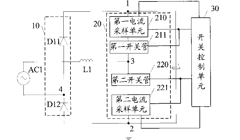
[0036] A totem pole bridgeless circuit system, the structure diagram is as follows figure 2 shown, including:

[0037] The first bridge arm unit 10 and the second bridge arm unit 20 connected in parallel between the first parallel connection point 1 and the second parallel connection point 2, the first bridge arm unit 10 includes the first and second bridge arm units connected in series in the same direction. Diode D11 and D12 of the second diode, that is, the anode of the first diode D11 in the figure is connected to the cathode of the second diode D12; the second bridge arm unit 20 includes the first A switch tube 211 and a second switch tube 220; a power supply AC1 and an inductance L1 are connected between the first connection point 4 between the two diodes and the second connection point 3 between the two switch tubes, and the system also includes a switch control Unit 30, and the second bridge arm unit 20 also includes:

[0038] Two current sampling units, wherein the...

Embodiment 2

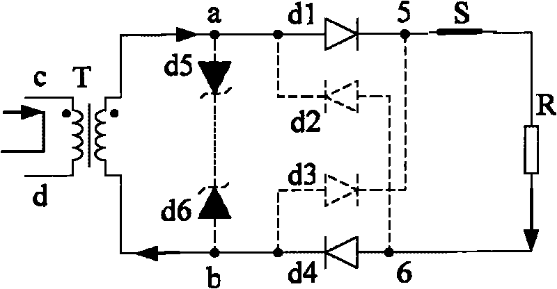
[0071] A current sampling device, the system of this embodiment can be used in the sampling of power electronic AC rectified current, and can also be used in the sampling of multi-phase AC rectified current, the schematic diagram of the structure is as follows Figures 3a to 3d shown, including:

[0072] A current transformer T, two homopolarly interconnected Zener diodes d5 and d6 (cathode interconnection in the figure), four diodes d1 to d4, a sampling switch tube S and a sampling resistor R, the current transformer T includes primary winding and secondary winding;

[0073] The two diodes d1 and d3 are homopolarly connected in series to form a first sampling bridge; the other two diodes d2 and d4 are homopolarly connected in series to form a second sampling bridge, and the first sampling bridge and the second sampling bridge Among them, the diode included in one of the sampling bridges is connected to the anode, and the diode included in the other sampling bridge is connect...

Embodiment 3

[0083] A current sampling device, the system of this embodiment can be used in the sampling of power electronic AC rectified current, and can also be used in the sampling of multi-phase AC rectified current, the schematic diagram of the structure is as follows Figures 4a to 4d shown, including:

[0084] Current transformer T1, two zener diodes d9 and d10 interconnected with the same pole (cathode interconnection in the figure), two diodes d7 and d8, sampling switch tube S' and sampling resistor R1; the current transformer T1 Including the primary winding and two secondary windings connected to the winding terminal s;

[0085] The two ends p and q of the primary winding of the current transformer T1 are connected to the circuit to be sampled;

[0086] Between the winding terminal s of the first secondary winding of the two secondary windings and the other terminal 7, there are the sampling switch S', the sampling resistor R1 and a diode connected in series d7; between the tw...


PUM


Abstract

The embodiment of the invention discloses a totem-pole bridgeless circuit system and a current sampling device, and is applied in the technical field of electricity supply. The circuit system comprises a switch control unit, a second bridge arm unit and two current sampling units added in the bridge unit, wherein the switching on / off of a first switching tube and a second switching tube in the second bridge arm unit are respectively controlled by the current sampled by the switch control unit through a first current sampling unit and a second current sampling unit. Compared with the prior art, the switching on / off of the switching tubes is controlled by the current sampled by the current sampling unit in the system, the difficulty on controlling the switching tube in the totem-pole bridgeless circuit system is reduced, and the utilization ratio of the totem-pole bridgeless circuit system is improved.

Description

technical field [0001] The invention relates to the technical field of power supply, in particular to a totem pole bridgeless circuit system and a current sampling device. Background technique [0002] In a power supply system, the conversion efficiency of the power supply is important. The high-efficiency power conversion systems in the prior art include a bridgeless power factor correction (PFC) circuit system and a resonant circuit (LLC) system. And the totem pole bridgeless boost conversion circuit system (hereinafter referred to as the totem pole bridgeless circuit system) is a kind of bridgeless PFC circuit system, such as figure 1 As shown, in the totem pole bridgeless boost conversion circuit system: the first bridge arm unit, the second bridge arm unit and the capacitor C are connected in parallel with each other, and one end of the connection is grounded; there are two in the first bridge arm unit Diodes D1 and D2 connected in series in the same direction; there a...

Claims


Application Information

Patent Timeline
Patent Type & Authority Applications(China)
IPC IPC(8): H02M7/02H02M7/217G01R19/00
CPCH02M7/217
Inventor 陈文彬周岿田帆
Owner HUAWEI DIGITAL POWER TECH CO LTD
Why Eureka
Try Eureka