Method and device for time synchronization in passive optical network and passive optical network

A passive optical network, time synchronization technology, applied in the field of network communication, can solve the problems of inaccurate delay, asynchronous time between slave clock and master clock, etc.

Active Publication Date: 2010-05-12
HUAWEI TECH CO LTD
View PDF6 Cites 37 Cited by
  • Summary
  • Abstract
  • Description
  • Claims
  • Application Information

AI Technical Summary

Problems solved by technology

[0015] According to the method provided by the prior art, the method of calculating the delay is to assume that the delay between the PTP from the master clock to the slave clock is the same as the delay from the slave clock to the master clock, and in the actual situation , the delay from the master clock to the slave clock is not the same as the delay from the slave clock to the master clock, which makes the calculated delay inaccurate and causes the time of the slave clock to be out of sync with the master clock

Method used


Image

  • Method and device for time synchronization in passive optical network and passive optical network
  • Method and device for time synchronization in passive optical network and passive optical network
  • Method and device for time synchronization in passive optical network and passive optical network

Examples


Embodiment 1

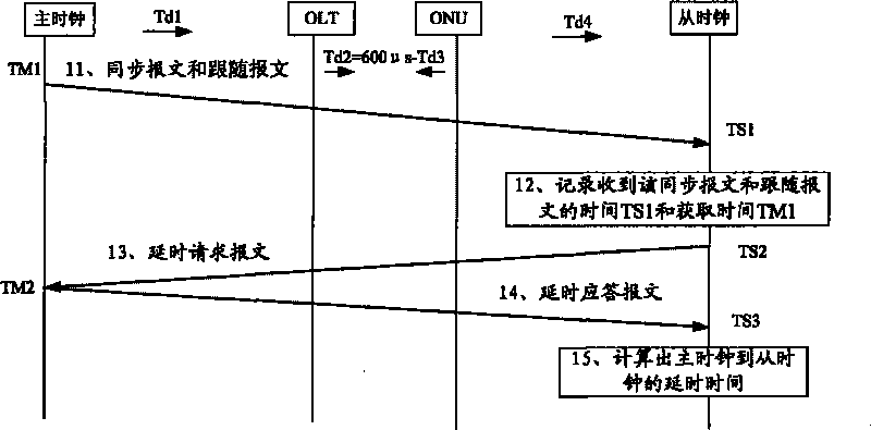
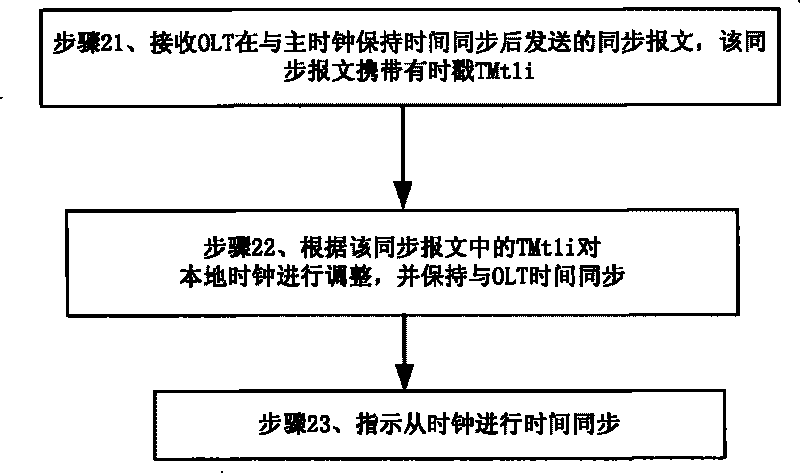
[0073] Embodiment 1: Embodiment 1 provides a method for time synchronization in a passive optical network. The technical scenario of this embodiment is that the passive optical network of this embodiment is GPON. The method is as follows figure 2 shown, including the following steps:

[0074] Step 21, receiving the synchronization message sent by the OLT after maintaining time synchronization with the master clock, the synchronization message carries a time stamp TMt1i, and the time stamp TMt1i is determined after the OLT completes time synchronization;

[0075] The specific method for keeping time synchronization between the OLT and the master clock in this step may be as follows: the OLT keeps time synchronization with the master clock through a PTP synchronization mechanism. The specific implementation method of the PTP synchronization mechanism can refer to the protocol IEEE 1588.

[0076] The specific method for the OLT in this step to keep synchronized with the master c...

Embodiment 2

[0091] Embodiment 2: This embodiment 2 provides a method for time synchronization in a passive optical network. The technical scenario of this embodiment is that the passive optical network of this embodiment is GPON, and the synchronization message is a unicast message. The timestamp carried by the synchronization message in this embodiment is TMt1i=TMt1+Tdi, and the structure of the synchronization message is as shown in Table 1:

[0092] Ocet

content

Description

1

ONU-ID

Address to one ONU

2

Message-ID

Message ID, identify SYC PLOAM

i

ssssssss

MSB of seconds, original timestamp

[0093] Ocet

content

Description

i+1

ssssssss

LSB of seconds, original timestamp

i+2

nnnnnnnn

MSB of nanoseconds, original timestamp

i+3

nnnnnnnn

i+4

nnnnnnnn

i+5

nnnnnnnn

LSB of nanoseconds, original tim...

Embodiment 3

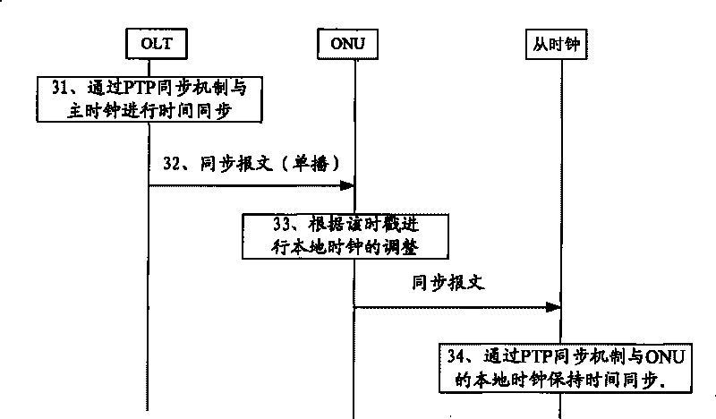
[0105] Embodiment 3: This embodiment 3 provides a method for time synchronization in a passive optical network. The technical scenario of this embodiment is that the passive optical network of this embodiment is GPON, and the synchronization message is a multicast synchronization message. The time stamp TMt1i=TMt1 carried by the synchronization message, of course, may also be a broadcast or unicast synchronization message in actual situations. When it is a unicast synchronization message, the structure of the synchronization message is as shown in Table 1 above As shown, when it is a multicast or broadcast synchronous message, the structure of the synchronous message is as shown in Table 2:

[0106] Ocet

content

Description

1

0

Address to one all ONU

2

Message-ID

Message ID, identify SYC PLOAM

i

ssssssss

MSB of seconds, original timestamp

i+1

ssssssss

LSB of seconds, ...


PUM


Abstract

The implementation method of the invention provides a method and a device for time synchronization in a passive optical network and the passive optical network. The method and the device belong to the field of network communication. The method comprises the following steps: receiving a synchronous message sent after an optical line terminal OLT maintains time synchronization with a master clock, wherein the synchronous message carries timestamps TMtil determined after the OLT completes the time synchronization; and adjusting a local clock according to the timestamps to enable ONU/ONT to maintain the time synchronization with the OLT, and instructing the ONU/ONT to perform the time synchronization from the clocks after maintaining the time synchronization with the OLT. The implementation method of the invention also provides a device and a system for the time synchronization in the passive optical network, and the system and the method have the advantage of maintaining synchronization of the master clock and a slave clock.

Description

technical field [0001] The invention relates to the field of network communication, in particular to a method and device for time synchronization in a passive optical network and the passive optical network. Background technique [0002] Passive Optical Network (PON) technology is a point-to-multipoint optical fiber transmission and access technology. In the PON system, the optical line terminal (Optical Line Terminal, OLT) to the optical network unit / optical network terminal (Optical Network Unit / Optical Network Terminal, ONU / ONT) is in the downlink direction, using Time Division Mulipex (TDM) technology; the transmission from ONU / ONT to OLT is in the uplink direction, using Time Division Multiple Access (Time Division Multiple Access) technology. Division Multiple Access, TDMA) technology. In order to synchronize the time of each device in the PON system, it is necessary to ensure that the master clock (Master Clock, MC) and the slave clock (Slave Clock, SC) have the same...

Claims


Application Information

Patent Timeline
Patent Type & Authority Applications(China)
IPC IPC(8): H04J3/06H04Q11/00
CPCH04J3/0664H04Q2011/0079H04J3/0667H04J3/0673H04Q11/0067H04Q2011/0088
Inventor 赵峻李三中
Owner HUAWEI TECH CO LTD
Why Eureka
Try Eureka