LED drive circuit of source driver with change of output voltage and induction quantity keeping constant current

A technology of LED driving and output voltage, applied in the direction of electric lamp circuit layout, electric light source, light source, etc., can solve the problem of low stability, output current easily affected by inductance and output voltage, increase the complexity of system design and the cost of inductance and other issues to achieve the effect of improving stability, reducing complexity and cost

Active Publication Date: 2010-05-12
SHANGHAI BRIGHT POWER SEMICONDUCTOR CO LTD
View PDF2 Cites 54 Cited by
  • Summary
  • Abstract
  • Description
  • Claims
  • Application Information

AI Technical Summary

Problems solved by technology

[0004] In the above-mentioned traditional drive circuit, there are the following disadvantages: the drive circuit controls the peak current and ripple current to keep the output current constant, the peak current is determined by the comparator 11, the reference voltage V1 and the sampling resistor RCS, the inductor current drop slope is related to the output voltage Vout is directly proportional to the inductance L, and the ripple current Ipp and the output average current Iout are respectively expressed by the following formula:
[0008] It can be seen from the above that the average output current of the traditional LED drive circuit changes with the output voltage and inductance, the output current is easily affected by the inductance and output voltage, and the stability is low, which increases the complexity of the system design and the inductance. cost

Method used


Image

  • LED drive circuit of source driver with change of output voltage and induction quantity keeping constant current
  • LED drive circuit of source driver with change of output voltage and induction quantity keeping constant current
  • LED drive circuit of source driver with change of output voltage and induction quantity keeping constant current

Examples


Embodiment Construction

[0023] In the following, preferred embodiments according to the present invention will be described in detail with reference to the accompanying drawings.

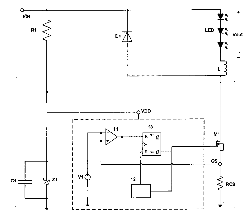
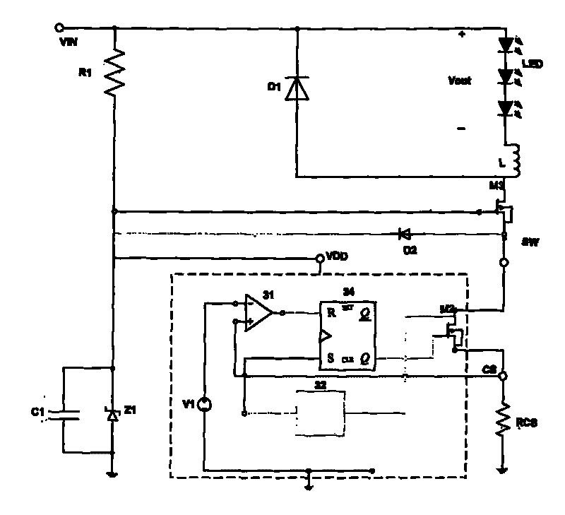
[0024] image 3 Schematically shows an LED driving circuit according to a preferred embodiment of the present invention. refer to image 3 , similar to the prior art, a resistor R1 and a voltage regulator tube Z1 are connected in series between the power supply VIN and the ground, the positive pole of the voltage regulator tube Z1 is connected to the ground, the negative pole of the voltage regulator tube Z1 is connected to one end of the resistor R1, and the resistor The other end of R1 is connected to the power supply VIN, the capacitor C1 is connected in parallel to both ends of the Zener tube Z1, the negative pole of the freewheeling diode D1 is connected to the positive pole of the load LED and the power supply VIN, and the positive pole of the freewheeling diode D1 is connected to the first pole of the inductor L O...


PUM


Abstract

The invention relates to an LED drive circuit of a source driver with the change of the output voltage and the induction quantity keeping constant current, which comprises a resistor R1, a voltage stabilizing tube, a capacitor, a flywheel diode D1 and an inductor and also comprises a first MOS transistor, wherein a grid electrode is connected with the negative pole of the voltage stabilizing tube, a drain electrode is connected between the inductor and the D1, a source electrode is connected with the positive pole of a current feed diode D2, and the negative pole of the D2 is connected with the negative pole of the voltage stabilizing tube; the source electrode drives a control circuit, and the control circuit comprises a second transistor, an RS trigger, a comparator and an inductive current zero-crossing detector. When the inductive current zero-crossing detector detects that inductive current crosses zero, the inductive current zero-crossing detector generates a setting signal and outputs the signal to the S input end of the RS trigger, so the second transistor is conducted; when output current is increased to enable the voltage of the positive input end of the comparator to be equal to reference voltage, the comparator turns over and controls the second transistor to be closed. According to the drive circuit, the output current is free from the influence of the induction quantity and the output voltage, the stability is enhanced, and the complexity and the cost of the circuit are lowered.

Description

technical field [0001] The invention relates to an LED driving circuit, in particular to an LED driving circuit with improved output current stability. Background technique [0002] figure 1 is a schematic diagram of a traditional LED drive circuit. Such as figure 1 As shown, the resistor R1 and the voltage regulator tube Z1 are connected in series between the power supply VIN and the ground, the positive pole of the voltage regulator tube Z1 is connected to the ground, the negative pole of the voltage regulator tube Z1 is connected to one end of the resistor R1, and the other end of the resistor R1 is connected to The power supply VIN; the capacitor C1 is connected in parallel to both ends of the Zener tube Z1; the negative pole of the freewheeling diode D1 is connected to the positive pole of the load LED and the power supply VIN, and the positive pole of the freewheeling diode D1 is connected to the first end of the inductor L, and the inductor L The second end is conn...

Claims


Application Information

Patent Timeline
Patent Type & Authority Applications(China)
IPC IPC(8): H05B37/02
Inventor 赵新江胡黎强张义
Owner SHANGHAI BRIGHT POWER SEMICONDUCTOR CO LTD
Why Eureka
Try Eureka