
Angular position sensor

一种角位置、传感器的技术,应用在磁传感器阵列、转换传感器输出、仪器等方向,能够解决传感器易受热损伤等问题,达到具有鲁棒性的效果

Active Publication Date: 2010-05-12
HYDRO AIRE AEROSPACE CORP
View PDF0 Cites 30 Cited by
  • Summary
  • Abstract
  • Description
  • Claims
  • Application Information

AI Technical Summary

Problems solved by technology

The use of Hall sensors has also been proposed before, but the configuration considered makes the sensor particularly susceptible to thermal damage and requires an excessive number of magnets and sensors to achieve the required accuracy

Method used


Image

  • Angular position sensor
  • Angular position sensor
  • Angular position sensor

Examples


Embodiment Construction

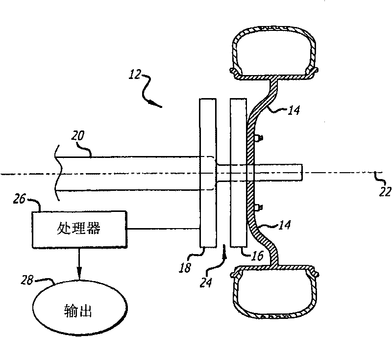
[0013] The invention relates to an angular position sensor which can be easily adapted eg on a wheel and used to control an antilock or antiskid braking system of such a wheel. System 12 is shown very broadly and schematically at figure 1 , wherein a wheel 14 has a target disc 16 associated therewith so as to rotate in unison, while a fixed sensor plate 18 is secured to a non-rotating shaft 20 or other support element. In the presently preferred embodiment, a circular target disk and a circular sensor plate are centered on a common axis 22 and separated by a small air gap 24 . One or more processors 26 convert the data generated by the sensor boards into usable outputs, such as angular position, rotational rate, or wheel speed.

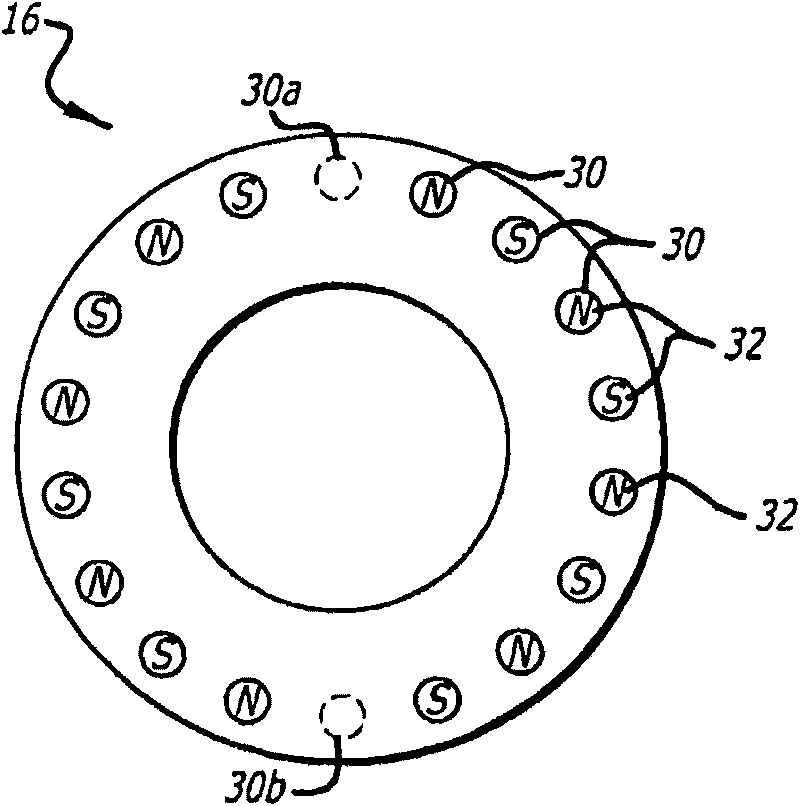
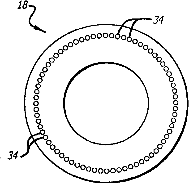
[0014] exist figure 2 In the schematically illustrated preferred embodiment, the target disk 16 has a total of 18 magnet positions 30 equally spaced around the circumference of the disk in angular increments of 20 degrees, with 16 such positions ar...


PUM


Abstract

An angular position sensor (24) and method that relies on a stationary- circular array of Hall sensors (18) and a rotatable circular array of magnets (16) arranged about a common axis (22). A periodic and simultaneous reading of all of the Hall sensor outputs is used to determine angular velocity.

Description

[0001] Cross References to Related Applications [0002] This application claims priority to US Provisional Application No. 60 / 933,340, filed June 6, 2007, which is hereby incorporated by reference in its entirety. technical field [0003] The present invention relates generally to angular position sensors and, more particularly, to sensors capable of very precise angular position determination in very harsh environments. Background technique [0004] Precisely determining the angular position of one component relative to another is critical in many applications. Furthermore, precise determination of angular position allows precise calculation of angular velocity and acceleration, which is crucial for efficient operation of high performance antilock or antiskid braking systems, for example. Components of brake systems can be exposed to quite extreme conditions, including high temperatures, vibration and shock loads, as well as water and dust contamination. Such conditions ...

Claims


Application Information

Patent Timeline
Patent Type & Authority Applications(China)
IPC IPC(8): B60T8/171B60T8/32G01P3/487
CPCG01P3/487B60T8/171B60T8/329G01D5/145G01R33/0094
Inventor M·扎克
Owner HYDRO AIRE AEROSPACE CORP
Learn More