Vibration-damping seat

A seat and backrest technology, applied in vehicle seats, seat suspension devices, special positions of vehicles, etc., can solve problems such as motion sickness, poor ventilation of foam blocks, irritability and discomfort, and achieve good applicability and vibration reduction effect. Good, the effect of improving comfort

Active Publication Date: 2010-05-19
南通星维海威精密机械有限公司
0 Cites 17 Cited by

AI-Extracted Technical Summary

Problems solved by technology

At present, in order to improve the noise and vibration performance of automobiles in the domestic and foreign automobile industries, major companies have successively developed emerging NVH technology products such as semi-active suspensions, active suspensions, air springs, hydraulic mounts, and variable magnetic flow hydraulic mounts. It also introduces hydraulic and electronic technology into the NVH field, overcoming the defect that traditional mechanisms cannot adapt to improve vehicle performance
As the final transmission object of the user, the seat has a good or bad vibration isolation performance, which directly affects the comfort of the occupants, thereby affecting the sales of automobiles.
[0003] Traditional seats generally use springs and (or) foamed plastics to dampen vibrations, and this damping material itself has some shortcomings: the foamed plastics block has po...

Method used

Also be provided with the upper locator 7 that can fix spring 6 and the lower locator 8 between spring 6 and upper support 2 and lower support 1, upper locator 7 and lower locator 8 are connected with upper support 2 respectively. It is fixedly connected with the lower support 1. The upper positioning part 7 and the lower positioning part 8 prevent the spring 6 from moving during use, so as to ensure the accuracy of the spring 6's elastic force point. A rubber pad 9 is also provided between the spring 6 and the upper positioning member 7 and the lower positioning member 8 . The rubber pad 9 can play a certain role in increasing the stressed area.
The main operating principle of this device is as follows: automobile all can make car body vibrate when bumpy road surface and violent speed change, and vibration is passed on the lower support 1 of seat by each parts on car body, and lower support 1 is transmitt...

Abstract

The invention provides a vibration-damping seat which belongs to the technical field of machinery. The invention solves the technical problems of poor vibration-damping effect, easy exposure to directional influence of impact force and the like found in the vibration-damping seat of the traditional automobile. The vibration-damping seat comprises a lower supporting seat, an upper supporting seat and a backrest which is connected with the upper supporting seat, wherein an intersection component is arranged between both sides of the upper supporting seat and the lower supporting seat, a spring is arranged between the upper supporting seat and the lower supporting seat, and a plurality of dampers are symmetrically distributed between the upper supporting seat and the lower supporting seat. The vibration-damping seat can effectively damp the impact of the front direction and the back direction of the seat and has good applicability; buffering can be realized prior to vibration damping, and the vibration-damping effect is good; and the elevation of the backrest is adjustable, and the comfort of the seat is enhanced.

Application Domain

Seat suspension devices

Technology Topic

Image

  • Vibration-damping seat
  • Vibration-damping seat
  • Vibration-damping seat

Examples

  • Experimental program(1)

Example Embodiment

[0021] The following are specific embodiments of the present invention in conjunction with the accompanying drawings to further describe the technical solutions of the present invention, but the present invention is not limited to these embodiments.
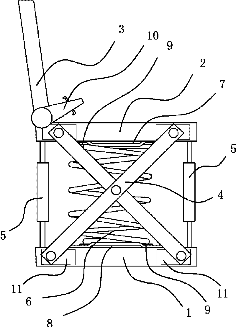
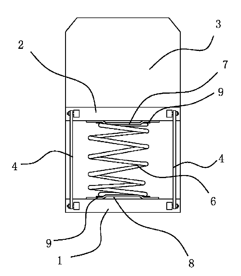
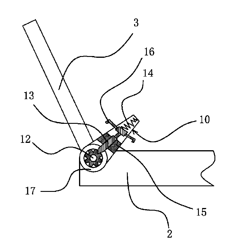
[0022] Such as figure 1 with figure 2 As shown, the damping seat includes a lower support 1, an upper support 2 and a backrest 3 connected to the upper support 2. The connection between the backrest 3 and the upper support 2 is provided with an adjuster 10 capable of adjusting the elevation angle of the backrest 3. As the body of the user is different, the required elevation angle of the backrest 3 is different, and the adjuster 10 can adjust the elevation angle of the backrest 3 according to the actual needs of the user. A spring 6 is provided between the middle of the upper support 2 and the lower support 1, and a number of dampers 5 are symmetrically distributed on the front and rear sides between the upper support 2 and the lower support 1. In this embodiment, the number of dampers 5 is two, but as another solution, it may be more than two. The most important impact of a car comes from acceleration or sudden braking. With dampers 5 installed on the front and rear sides of the seat, the vibration caused by acceleration or sudden braking can be reduced to the greatest extent. Two cross members 4 are respectively provided on the left and right sides between the upper support 2 and the lower support 1. The cross member 4 includes two hinged sliding rods in the middle. The two ends of the sliding rods are respectively arranged on the upper support 2 and the lower support. In the sliding grooves 11 on the front and rear sides of the support 1.
[0023] Between the spring 6 and the upper support 2 and the lower support 1 are also provided an upper positioning member 7 and a lower positioning member 8 capable of fixing the spring 6. The upper positioning member 7 and the lower positioning member 8 are respectively connected to the upper support 2 and the lower support Block 1 is firmly connected. The upper positioning member 7 and the lower positioning member 8 prevent the spring 6 from moving during use and ensure the accuracy of the elastic force point of the spring 6. A rubber pad 9 is also provided between the spring 6 and the upper positioning member 7 and the lower positioning member 8. The rubber pad 9 can play a certain role in increasing the force area.
[0024] Such as image 3 As shown, the adjuster 10 includes a fixing frame 17 fixed on the upper support 2 and a gear 12 fixed on the backrest 3. The gear 12 passes through the fixing frame 17, and the fixing frame 17 is provided with a thimble 13 and a guide Block 15, the thimble 13 is provided with handles 16 on both sides, the end of the thimble 13 is stuck between the two teeth of the gear 12, the thimble 13 is slidably connected with the guide block 15 and can be separated from the gear 12 when the thimble 13 slides along the guide block 15, A return spring 14 capable of resetting the thimble 13 is arranged between the tail of the thimble 13 and the fixing frame 17. When the elevation angle of the backrest 3 needs to be adjusted, manually pull the handle 16 to make the thimble 13 work along the guide block 15 to overcome the return spring 14, and the thimble 13 and the gear 12 are separated. At this time, the angle of the backrest 3 can be manually adjusted. When the thimble 13 is opened, the return spring 14 pushes the thimble 13 to be caught between the two teeth of the gear 12 to fix the gear 12 circumferentially. Because the gear 12 and the backrest 3 are fixedly connected, the backrest 3 and the upper support 2 are locked at this time.
[0025] The main working principle of this device is as follows: the car body will vibrate when the road is bumpy and the speed changes drastically. The vibration is transmitted to the lower support 1 of the seat through various parts on the car body, and the lower support 1 is passed through springs. 6. The damper 5 and the cross member 4 are transferred to the upper support 2. In this process, the two ends of the two sliding rods of the cross member 4 slide in the chute 11 and change the distance between the upper support 2 and the lower support 1. The spring 6 converts the vibration of large energy into multiple vibrations. For small energy vibration, the damper 5 reduces the number of small energy vibrations and eliminates vibration. When the user sits on the upper support 2 and the vibration on the vehicle body is transmitted to the user, most of the vibration has been eliminated, which improves the comfort of the user. The two dampers 5 of the device are symmetrically distributed on the front and rear sides between the upper support 2 and the lower support 1, and the vibration damping seat can be well cushioned in both front and rear directions, and vibration can be greatly eliminated.
[0026] The specific embodiments described herein are merely examples to illustrate the spirit of the present invention. Those skilled in the art to which the present invention pertains can make various modifications or additions to the specific embodiments described or use similar alternatives, but they will not deviate from the spirit of the present invention or exceed the definition of the appended claims. Range.

PUM

no PUM

Description & Claims & Application Information

We can also present the details of the Description, Claims and Application information to help users get a comprehensive understanding of the technical details of the patent, such as background art, summary of invention, brief description of drawings, description of embodiments, and other original content. On the other hand, users can also determine the specific scope of protection of the technology through the list of claims; as well as understand the changes in the life cycle of the technology with the presentation of the patent timeline. Login to view more.

Similar technology patents

Classification and recommendation of technical efficacy words

  • Good vibration reduction effect
  • Good applicability

Vibration damping rubber bushing

InactiveUS20060214341A1Good vibration reduction effectResilient suspensionsRubber-like material springsEngineeringElastomer
Owner:DAI NIPPON TORYO CO LTD

Manufacturing method of flexible heat-sensitive thin film resistor array

ActiveCN101950644AGood applicabilityGood insulation performanceNegative temperature coefficient thermistorsPositive temperature coefficient thermistorsPrepolymerSheet resistance
Owner:NORTHWESTERN POLYTECHNICAL UNIV

Motion blur removing method based on close shot remote sensing

InactiveCN106934769ACalculation and recovery results are accurateGood applicabilityImage enhancementImage analysisOptical flow estimationThree dimensional data
Owner:WUHAN UNIV OF TECH
Why Eureka
Try Eureka