Speed regulation controller
A speed control controller and speed control technology, applied in bicycle control systems, bicycle gear transmission mechanisms, bicycle accessories, etc., can solve overspeed, inconvenient installation and matching, and inability to control multi-level speed regulation and shift positions to assist bicycles to travel and other problems, to achieve the effect of wide application range, flexible control and simple structure
- Summary
- Abstract
- Description
- Claims
- Application Information
AI Technical Summary
Problems solved by technology
Method used
Image

Examples
Embodiment 1
[0021] Embodiment 1: Take the power-assisted bicycle driven by a mid-mounted electric motor as an example for illustration.
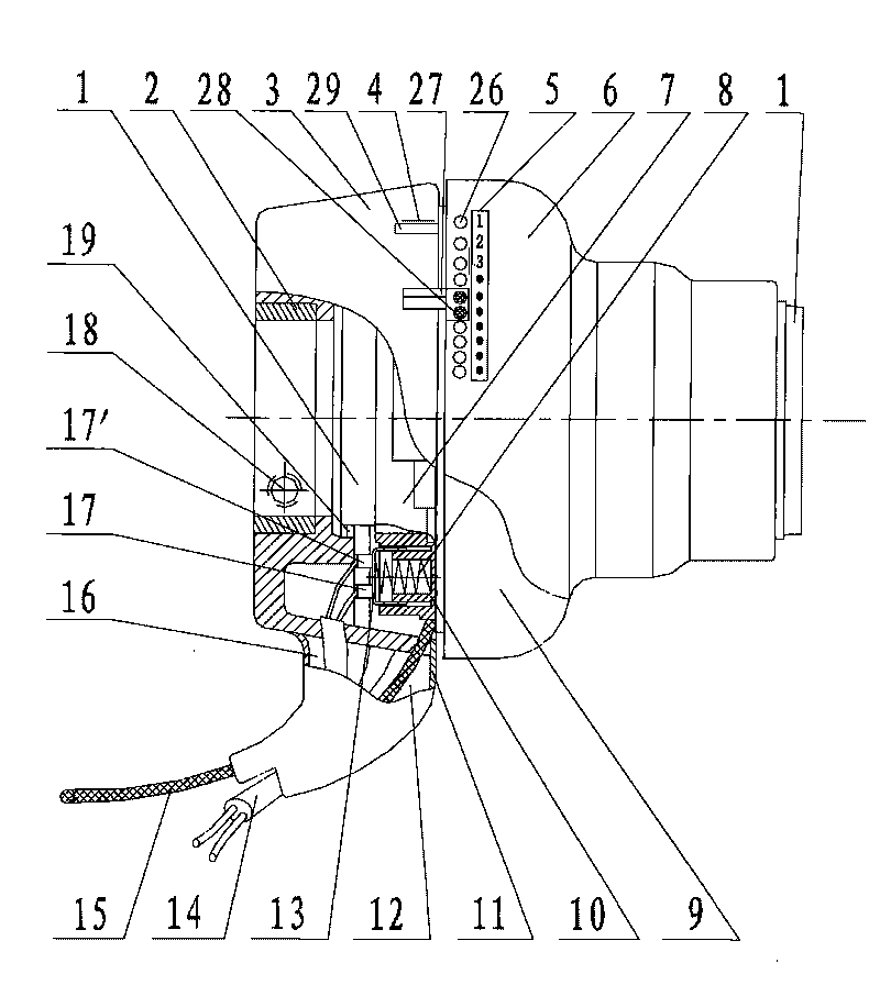
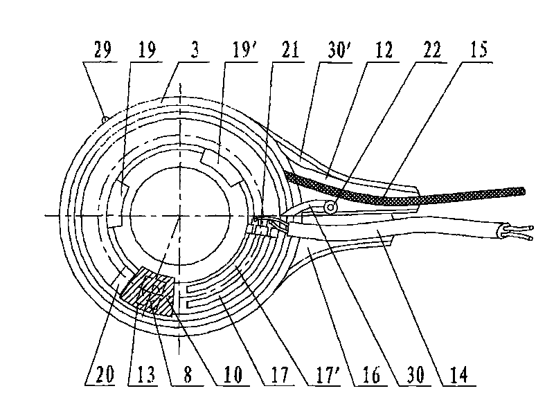
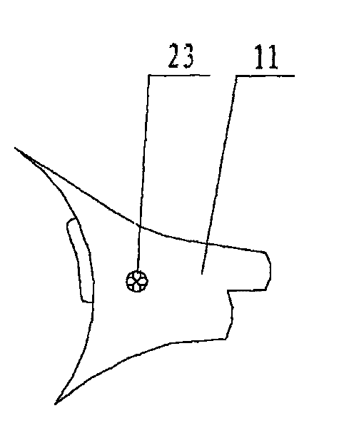
[0022] like Figure 1 to Figure 4 Shown: the speed controller is installed on the left side of the handlebar of the electric motor power-assisted bicycle in the center, the electrical control switch 10 adopts a mechanical switch, and the switch dynamic contact 13 and the switch spring 8 are arranged on the steel rope locator 7 (or set on the rotating device 9), and is integrated with the steel rope locator 7 (or rotating device 9) (or the split is fixed as a whole by a clip) and rotates together, and one end of the steel rope 15 is fixed on the steel rope locator 7 In the fixed groove 24 on the top, the steel rope locator 7 rotates and drives the steel rope 15 to rotate forward and backward around its steel rope guide groove 25 circumference for telescopic shifting and speed regulation, and the steel rope is set on the steel rope output groove 12 and th...
Embodiment 2
[0030] Embodiment 2: Take the power-assisted bicycle driven by a mid-mounted electric motor as an example for illustration.
[0031] like Figure 1 to Figure 4 As shown: the switch dynamic contact 13 of the electrical control switch 10 is arranged on the fixing device 3 and the switch static contact 17, 17' is integral or split and fixed into one by the card position, and the electrical control switch 10 can also be It can be used integrally with the fixing device 3 or used as a component on the fixing device 3 by clamping and retaining; at this time, the rotating device 9 can be used through the push rod (the contact end of the push rod is designed to be spherical or used in conjunction with the sphere to reduce sliding frictional resistance) contact with the switch dynamic contact 13 of the electrical control switch 10 and the switch spring 8, and the projection and the groove provided on the rotating device 9 or the steel rope locator 7 mortgage or release the ejector rod t...
Embodiment 3
[0032] Embodiment 3: Take a fuel-assisted bicycle driven by a mid-mounted fuel motor as an example for illustration.
[0033] like Figure 1 to Figure 4 Shown: the speed control controller of the present invention is installed on the handlebar of the fuel-assisted bicycle driven by the central fuel motor, and the brake control switch and the handle are arranged on the left and right sides of the handlebar at the same time, and the switch on the speed control controller is controlled Line 14 is connected with the brake control switch line on the left or right side (or directly connected with the brake signal line of the fuel motor controller), and at this moment the electrical control switch 10 is equivalent to the effect of the brake control switch. Its working principle, method of use and advantages are exactly the same as those in Embodiment 1.
PUM
 Abstract
Description
Claims
Application Information
 - R&D Engineer
- R&D Manager
- IP Professional
- Industry Leading Data Capabilities
- Powerful AI technology
- Patent DNA Extraction
Browse by: Latest US Patents, China's latest patents, Technical Efficacy Thesaurus, Application Domain, Technology Topic.
© 2024 PatSnap. All rights reserved.Legal|Privacy policy|Modern Slavery Act Transparency Statement|Sitemap