
Biogas residue biogas slurry processor

A processor and biogas slurry technology, applied in water/sewage multi-stage treatment, water/sludge/sewage treatment, flocculation/sedimentation water/sewage treatment, etc. To achieve the effect of high filtration rate of suspended organic matter

Inactive Publication Date: 2012-02-01
JIANGSU XINGNONG ENVIRONMENT PROTECTION TECH CO LTD
View PDF0 Cites 0 Cited by
  • Summary
  • Abstract
  • Description
  • Claims
  • Application Information

AI Technical Summary

Problems solved by technology

At the same time, a large amount of biogas residue and biogas slurry wastewater is produced. The sewage and organic matter content of these biogas residue and biogas slurry after solid-liquid separation are still high and cannot be discharged directly.

Method used

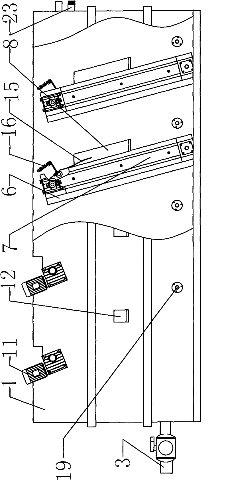
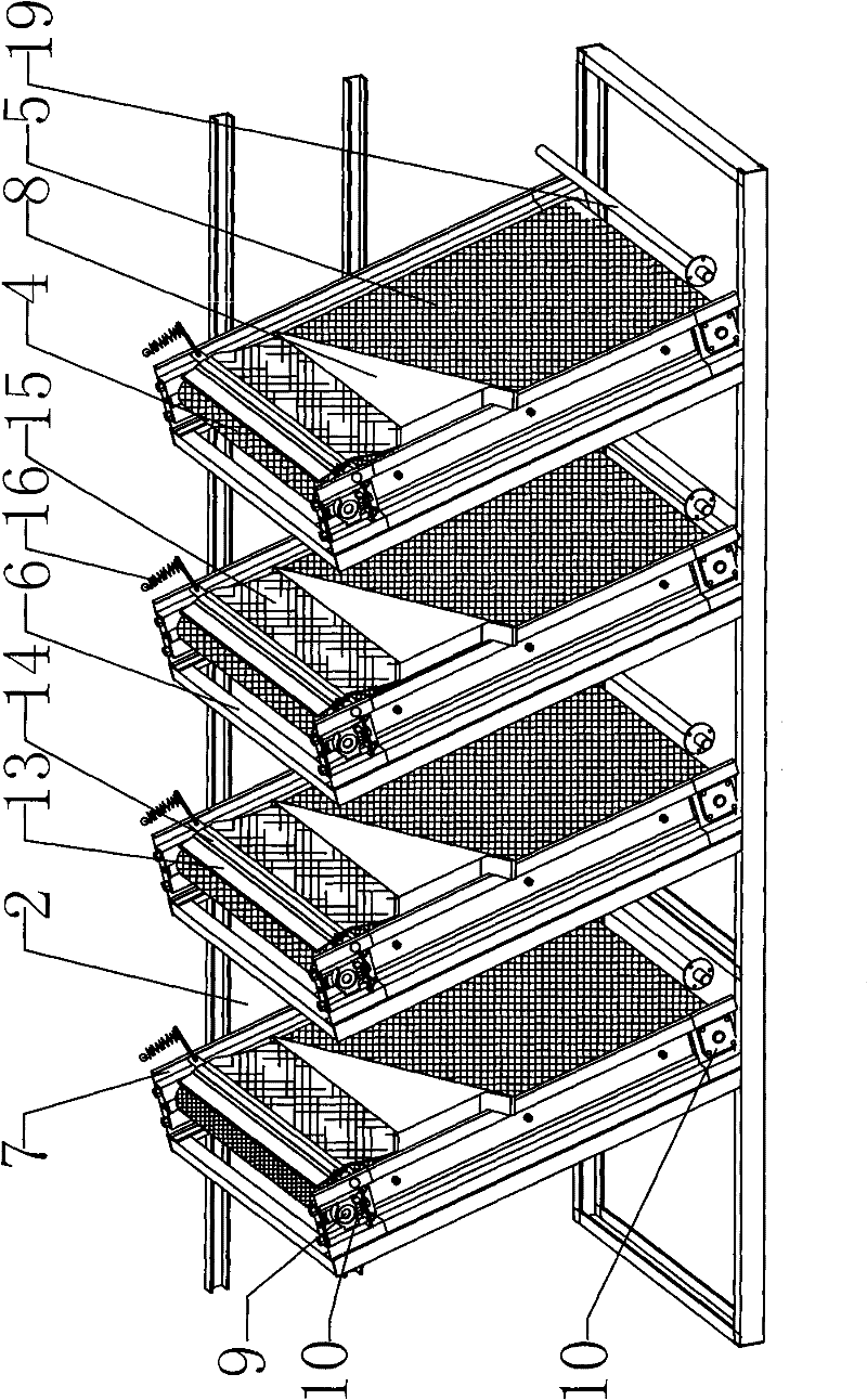
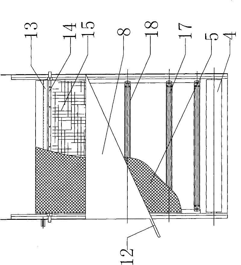

Image

  • Biogas residue biogas slurry processor
  • Biogas residue biogas slurry processor
  • Biogas residue biogas slurry processor

Examples


Embodiment 1

[0023] Such as figure 1 , 2 As shown in and 3, the biogas residue biogas slurry processor includes a box body 1 and a filter device, and the length direction of the box body 1 is respectively provided with a plurality of filter devices, and the box body space between each filter device forms a filter chamber section 2, the first The casing 1 of the first filter chamber section 2 is provided with a waste water inlet 23, and the bottom of the casing 1 of the last filter chamber section 2 is provided with a filtrate outlet 3, and each filter device is inclined towards the filtrate outlet direction and forms a horizontal line. Angle α, which is 70°. The filtering device includes a drum 4, a filter screen 5, a filter screen frame 6, a side plate 7, a sewage discharge tank 8 and a slag removal mechanism. The direction of the filtrate outlet 3 decreases step by step. The slag removal mechanism includes a scraper 13, a scraper shaft 14, a rubber plate 15 and a spring 16. Side plate...

Embodiment 2

[0025] Such as Figure 4 As shown, the aeration tube 19 of the present invention can be omitted, and as long as the stirring paddle 21 and the stirring motor 22 of the case cover 20 are arranged, the solution can be stirred and mixed. Other structures are with embodiment 1.

[0026] The invention works like this:

[0027] Turn on the motor 11 that drives the drum 4 to rotate, and inject waste water into the first filter chamber section 2. At this time, the drum 4 drives the filter screen 5 to filter the residue in the waste water, and uses the scraper 13 to scrape the filter residue into the sewage tank 8, From the second filter chamber section 2, put into each chamber section sewage treatment flocculant in proportion to purify, open the aeration pipe 19 at the bottom of the box body 1, and the stirring motor 22 at the upper end of the box cover 20, for each chamber section The solution is mixed and stirred, and the solution of each chamber segment treated with the flocculan...


PUM


Abstract

The invention relates to a processing machine for biogas residue and biogas slurry, which is characterized in that: the filter device includes a drum, a filter screen, a filter screen frame, a side plate, a sewage tank and a slag removal mechanism, and side walls are respectively fixed on the two side walls of the box body. The side plate is fixedly connected to the side of the filter frame on one side in the length direction of the box body. The two rollers are respectively fixed on the bearing seats at the upper and lower ends of the side plates on both sides through bearings. The motors fixed on the box body are connected, and a plurality of rotatable roller parts are evenly arranged on the side plates on both sides between the upper and lower rollers, and a filter screen is set between the upper and lower rollers. The net is placed on the outside of the idler; the sewage tank with a sewage outlet on the side of the box is fixed on the side of the side plate opposite to the filter frame, and the slag removal mechanism is set between the tops of the side plates on the side of the sewage tank. The invention has the advantages of: a durable and reliable biogas residue biogas slurry processor with high filtration rate of suspended organic matter.

Description

technical field [0001] The invention relates to the treatment of biogas residue and biogas slurry wastewater, in particular to a biogas residue and biogas slurry processing machine. Background technique [0002] At present, as the country enters a new stage of sustainable development with urban belts and rural areas, a series of policies and measures to support "three rural areas" have been introduced. In particular, the scope and scale of biogas projects have been continuously expanded, and the biogas treatment of manure has reached a considerable scale. At the same time, a large amount of biogas residue and biogas slurry wastewater is produced. The sewage and organic matter content of these biogas residue and biogas slurry after solid-liquid separation are still high and cannot be discharged directly. With the implementation of the one-vote veto system for environmental protection in the aquaculture industry, the treatment of biogas residue and biogas slurry in aquaculture...

Claims


Application Information

Patent Timeline
Patent Type & Authority Patents(China)
IPC IPC(8): C02F9/02C02F1/52
Inventor 邱建兴邱永发李冲赵国栋刘敏季松沈丹波缪明张意明
Owner JIANGSU XINGNONG ENVIRONMENT PROTECTION TECH CO LTD
Learn More