Electronic release bracket of electronic low pressure circuit breaker

A technology for low-voltage circuit breakers and electronic releases, which is applied to circuits, electrical components, and parts of protective switches. It can solve problems such as unreliable positioning, easy-to-burn transformers, and complicated bases, so as to ensure insulation performance, The effect of ensuring electrical safety and eliminating potential safety hazards

Active Publication Date: 2012-05-02
EATON HUINENG LOW-VOLTAGE ELECTRICAL (JIANGSU) CO LTD
View PDF4 Cites 0 Cited by
  • Summary
  • Abstract
  • Description
  • Claims
  • Application Information

AI Technical Summary

Problems solved by technology

[0003] The transformers of the current electronic circuit breakers are generally directly positioned in the limit slots matched with the base, so there are many limit devices on the base that cooperate with the transformers, which complicates the base; and the transformers have no special protection , the insulation strength of the main circuit of the circuit breaker is not enough, and it is easy to burn the transformer and cause a short circuit between phases in the case of a large current of the circuit breaker; the existing wiring method is that any transformer has a lead wire connected to the circuit board, and a certain number of The connecting wires of the circuit board are exposed outside the circuit board bracket, the wiring is disturbed, and there is no positioning. The wires are easy to be damaged during assembly and are easy to touch the main circuit of the circuit breaker, which has certain potential safety hazards; the existing circuit boards are generally installed directly on the There is no reliable positioning in the bracket of the electronic release, and the insulation strength with the main circuit is not enough, so there are certain potential safety hazards

Method used


Image

  • Electronic release bracket of electronic low pressure circuit breaker
  • Electronic release bracket of electronic low pressure circuit breaker
  • Electronic release bracket of electronic low pressure circuit breaker

Examples


Embodiment Construction

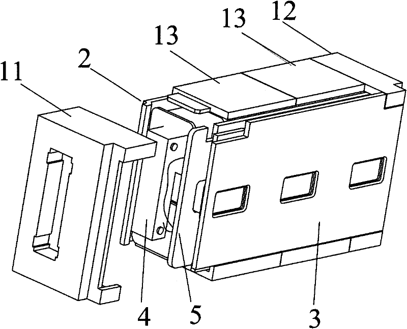
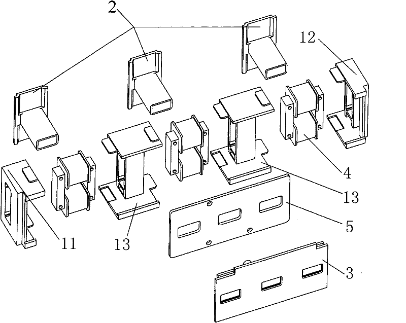
[0026] Such as figure 1 , 2 As shown, the electronic release bracket is composed of a first baffle 2, a second baffle 3, a first bracket 11, a second bracket 12 and at least two third brackets 13, the first baffle 2 and the second baffle 3 are respectively fixedly arranged on both sides of the bracket of the electronic trip unit, namely connected to both sides of the first bracket 11, the second bracket 12 and the third bracket 13. The first baffle 2 and the second baffle 3 are injection molded from plastic materials Or formed by other processing methods.

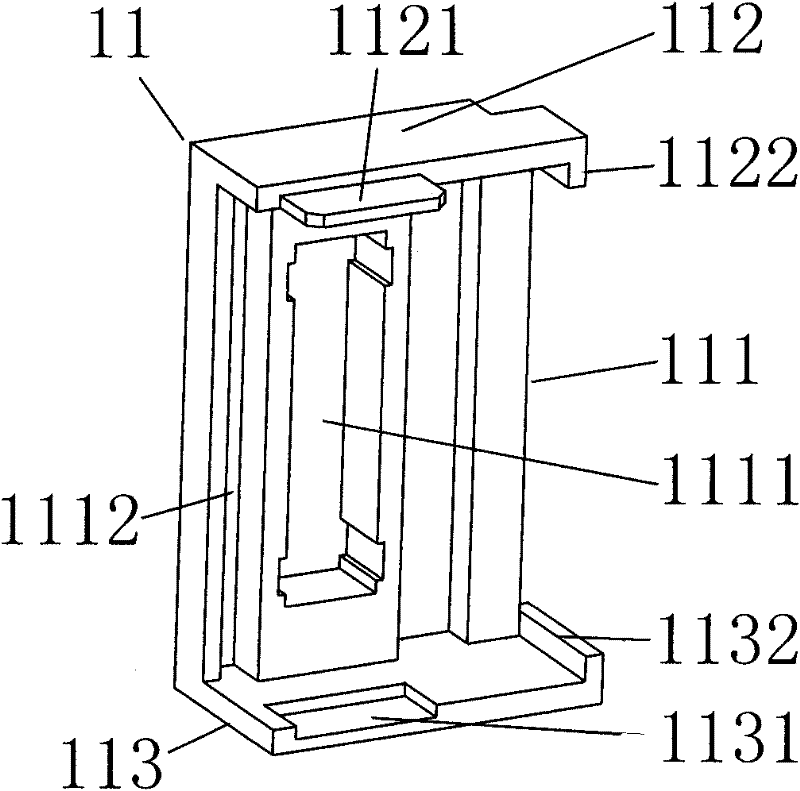
[0027] Such as image 3 As shown, the first bracket 11 has a U-shaped structure formed by a side wall 111 and a top wall 112 and a bottom wall 113 extending in the same direction along the two ends of the side wall 111. A groove 1111 is provided on the side wall 111. The groove 1111 can be a through groove or a blind groove. The contour of the groove 1111 matches the contour of the transformer 4 to fix the transformer 4. An e...


PUM


Abstract

The invention discloses an electronic release bracket of an electronic low pressure circuit breaker, the electronic release bracket is composed of U-shaped first and second brackets and at least two I-shaped third brackets which are life-and-right interconnected, a first baffle plate and a second baffle plate are connected to two sides of the three brackets respectively; the electronic release bracket with simple structure and reliable assembly can easily and flexibly reach the assembly requirement of the electronic release of tripole and quadrupole circuit breakers; a mutual inductor is completed enveloped in a mutual inductor bracket to acquire sufficient insulating strength with a main loop of the circuit breaker, thus guaranteeing electrical safety of the mutual inductor and thoroughly eradicating hidden safety hazard; parts of the electronic release can be entirely separated from the main loop of the circuit breaker in order to ensure adequate insulating property of the electronic release; and the reliable wiring and positioning inside the casing avoids the hidden safety hazard caused by the exposure of open wires.

Description

Technical field [0001] The invention relates to an electronic trip unit of an electronic low-voltage circuit breaker, and in particular to a bracket for installing the electronic trip unit. Background technique [0002] Low-voltage circuit breakers are generally commonly used for power distribution, motor protection, residual current protection and electronic circuit breakers. Electronic low-voltage circuit breakers have the functions of overload long delay, short circuit short delay, short circuit instantaneous and undervoltage protection. They are more comprehensive in function than ordinary thermal magnetic circuit breakers, and are more reliable and more reliable for distribution lines and electrical equipment. Comprehensive protection; various functions of electronic low-voltage circuit breakers are realized by electronic trippers. Electronic trippers include: transformers, circuit boards and actuators, as well as brackets that fix and connect the three. Each pole of the cir...

Claims


Application Information

Patent Timeline
Patent Type & Authority Patents(China)
IPC IPC(8): H01H71/02
Inventor 朱未东江长生陈咸任飞
Owner EATON HUINENG LOW-VOLTAGE ELECTRICAL (JIANGSU) CO LTD
Why Eureka
Try Eureka