LED control circuit and LED device

A control circuit and LED driving technology, applied in circuit layout, electric lamp circuit layout, lighting devices, etc., can solve problems such as burnout, complex circuit, and insecurity

Inactive Publication Date: 2013-10-23
OCEANS KING LIGHTING SCI&TECH CO LTD +1
View PDF4 Cites 0 Cited by
  • Summary
  • Abstract
  • Description
  • Claims
  • Application Information

AI Technical Summary

Problems solved by technology

[0003] The disadvantage of prior art 1 is that the constant current effect of the LED lamp 13 is greatly affected by the difference factors of components such as the single chip microcomputer 11 and the sampling circuit. phenomenon, then it is necessary to add a reasonable filter circuit in the sampling circuit, resulting in high cost and complicated circuit
[0004] figure 2 The circuit diagram of the LED drive control circuit provided by the prior art 2 is shown; the LED drive control circuit adopts a dedicated LDO analog chip 14 to simulate and control the LED lamp 13; in this way, it is easy to control the light of the LED lamp 13 to flicker, constant The flow effect is better; but the efficiency is low. In the case of a short circuit and a high input voltage, the LDO analog chip 14 is prone to heat, or even burned, resulting in unsafety; at the same time, the use of the LDO analog chip 14 causes the current output to the LED lamp 13 The size is fixed, and the constant current value of the output cannot be adjusted; the driving load power is small, and a single chip can drive a load within 1.5 watts

Method used


Image

  • LED control circuit and LED device
  • LED control circuit and LED device
  • LED control circuit and LED device

Examples


Embodiment Construction

[0025] In order to make the object, technical solution and advantages of the present invention clearer, the present invention will be further described in detail below in conjunction with the accompanying drawings and embodiments. It should be understood that the specific embodiments described here are only used to explain the present invention, not to limit the present invention.

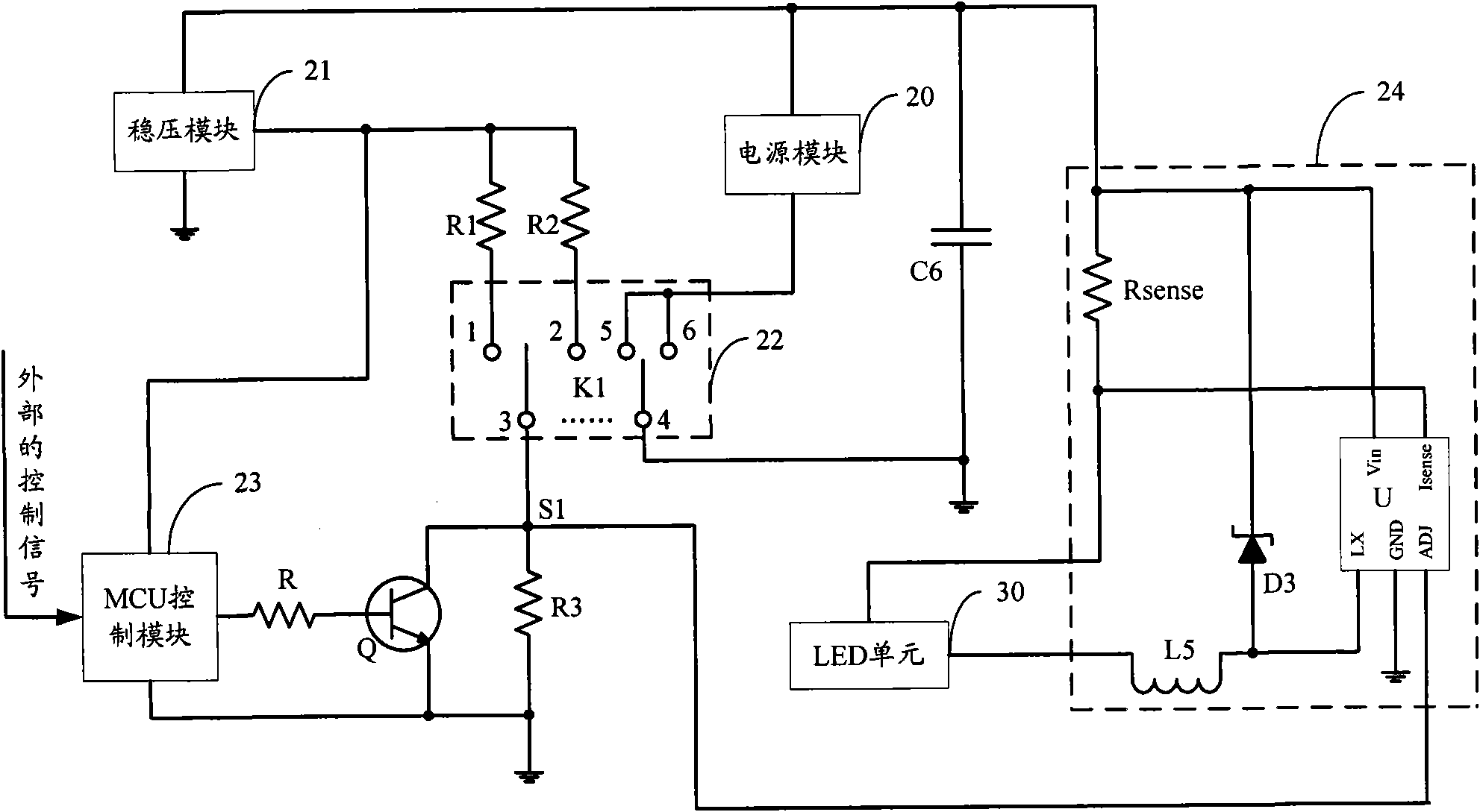
[0026] The LED control circuit provided by the embodiment of the present invention adopts a switch module to realize switching between constant current control and flicker control, and outputs a control signal with a fixed pulse width through the MCU control module to realize flicker control of the LED unit; The operating current of the unit is adjusted in real time to achieve the purpose of constant current control.

[0027] image 3 The circuit diagram of the LED control circuit provided by the embodiment of the present invention is shown. For the convenience of description, only the parts relat...


PUM


Abstract

The invention provides an LED control circuit and an LED device, belonging to the field of the LED driving. The LED control circuit comprises a power supply module, a voltage stabilizing module, a switch module, an MCU control module, a triode and at least one LED driving module. When the electrical level of the input end of the LED driving module is more than or equal to the set threshold, the LED driving module outputs a constant-current control signal to control the constant current of an LED unit, and when the electrical level of the input end of the LED driving module is less than the set threshold, the LED driving module shuts off the output of the constant current, and the pulse control signal outputted by the MCU control module controls the LED unit to flicker at set frequency. The LED control circuit of the invention switches the constant current control and the flicker control of the LED unit by adopting the switch module, controls the LED unit to flicker by adopting the MCU control module which outputs the control signal of fixed pulse width and adjusts the work current of the LED unit in time by adopting the LED driving module, thereby controlling the constant current of the LED unit.

Description

technical field [0001] The invention belongs to the field of LED driving, and in particular relates to an LED control circuit and an LED device. Background technique [0002] At present, there are two main types of isolation-free high-power LED constant-current drive circuits that use low-voltage DC power supply: figure 1 The circuit diagram of the LED drive control circuit provided by prior art 1 is shown; the LED drive control circuit includes a single-chip microcomputer 11 and a BUCK circuit 12, wherein the BUCK circuit 12 includes a MOS transistor Q0, an inductor L0, a capacitor C0, and a diode D0, wherein the MOS transistor Q0 The gate of the MOS transistor Q0 is connected to the PWM control signal output terminal 112 of the microcontroller 11, the source of the MOS transistor Q0 is connected to the power supply VCC, the drain of the MOS transistor Q0 is connected to the cathode of the diode D0, and the drain of the MOS transistor Q0 is also connected to the inductor L0...

Claims


Application Information

Patent Timeline
Patent Type & Authority Patents(China)
IPC IPC(8): H05B37/02F21S2/00F21V23/00F21Y101/02F21K9/20F21Y115/10
CPCY02B20/42Y02B20/40
Inventor 周明杰张玉平
Owner OCEANS KING LIGHTING SCI&TECH CO LTD
Why Eureka
Try Eureka