Device for treating particulate material
A technology for processing particles and shells, applied in powder suspension granulation, chemical/physical processes, chemical instruments and methods, etc., can solve problems such as difficult to find the entrance into the inner cavity, damage to static stability, etc. Achieve the effect of efficient heat transfer and economical process guidance
- Summary
- Abstract
- Description
- Claims
- Application Information
AI Technical Summary
Problems solved by technology
Method used
Image

Examples
Embodiment Construction
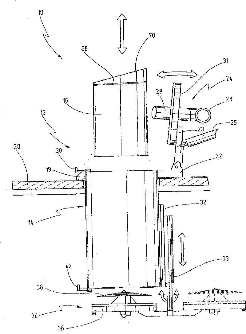
[0079] exist Figures 1 to 5 In the first embodiment shown, the device according to the invention for the treatment of granular material is denoted as a whole by the reference numeral 10 .
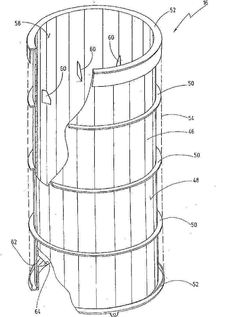
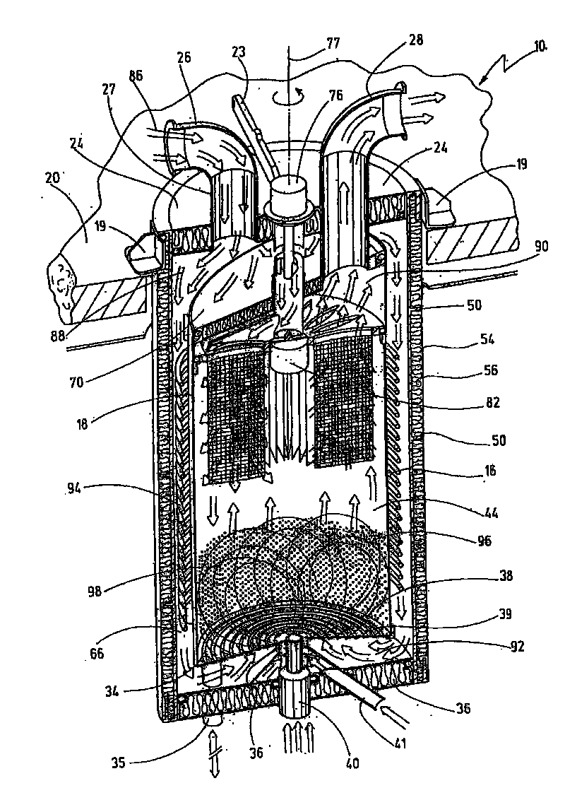
[0080] The device 10 has a housing 12 with a wall 14 . The wall portion 14 is composed of an outer wall 16 and an inner wall 18, wherein, in figure 1 How the inner wall 18 rises from the outer wall 16 is shown in . It can be seen that the outer diameter of the inner wall 18 is smaller than the inner diameter of the outer wall 16, so that when the inner wall 18 is inserted into the outer wall 16, an annular cavity 66 is formed between the inner wall 18 and the outer wall 16, for example from image 3 can be seen in the cross-sectional view. The outer wall 16 is mounted on a beam 20 such as a cover or an intermediate cover of the housing. A cover 24 is mounted beyond the upper end of the outer wall 16 via a holder 22 . The holder 22 has a rocker 23 which can be moved about a pivot axis ...
PUM
 Abstract
Description
Claims
Application Information
 - R&D
- Intellectual Property
- Life Sciences
- Materials
- Tech Scout
- Unparalleled Data Quality
- Higher Quality Content
- 60% Fewer Hallucinations
Browse by: Latest US Patents, China's latest patents, Technical Efficacy Thesaurus, Application Domain, Technology Topic, Popular Technical Reports.
© 2025 PatSnap. All rights reserved.Legal|Privacy policy|Modern Slavery Act Transparency Statement|Sitemap|About US| Contact US: help@patsnap.com