Fin type heat exchanger convenient to clean

A fin heat exchanger and heat exchanger technology, applied in the field of fin heat exchangers, can solve the problems of blockage, the fin heat exchanger cannot withstand high pressure, cannot be cleaned, etc., and achieves enhanced heat transfer effect, Good decompression and ensure the effect of heat exchange

Pending Publication Date: 2022-03-08
苏州荣轩环保有限公司
View PDF0 Cites 0 Cited by
  • Summary
  • Abstract
  • Description
  • Claims
  • Application Information

AI Technical Summary

Problems solved by technology

[0004] The present invention provides a finned heat exchanger that is convenient for decontamination, which can effectively solve the problems raised in the above-mentioned background technology. In the actual application process, the fin heat exchanger cannot withstand high pressure, and at the same time, several pipes are used for water supply and drainage treatment, so that when the inlet and outlet water pipes of the fin heat exchanger are blocked and dirt accumulates, it is easy to be unable to clean. dirty problem

Method used


Image

  • Fin type heat exchanger convenient to clean
  • Fin type heat exchanger convenient to clean
  • Fin type heat exchanger convenient to clean

Examples


Embodiment

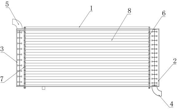
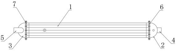
[0036] Example: such as Figure 1-3As shown, the present invention provides a technical solution, a finned heat exchanger that is convenient for decontamination, including a heat exchanger body 1, and one side of the heat exchanger body 1 is fixedly connected with a water inlet bearing for reducing the water inlet pressure. The pressure pipe 2, the other side end of the heat exchanger body 1 and the water inlet pressure pipe 2 are fixedly connected with the water outlet pressure pipe 3 to reduce the water outlet pressure, and the bottom end of the water inlet pressure pipe 2 is vertically fixed for further The water inlet pipe 4 and the top of the outlet pressure bearing pipe 3 are vertically fixedly connected with an outlet pipe 5 for drainage;

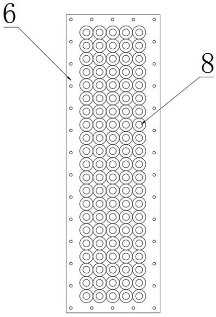
[0037] One side end of the water inlet pressure-bearing pipe 2 close to the heat exchanger body 1 is fixedly installed with an inlet water pressure-bearing flange 6 to withstand the water inlet pressure, and one side end of the water...


PUM


Abstract

A water inlet pressure-bearing pipe for reducing water inlet pressure is fixedly connected to one side end of a heat exchanger body, and a water outlet pressure-bearing pipe for reducing water outlet pressure is fixedly connected to the position, corresponding to the water inlet pressure-bearing pipe, of the other side end of the heat exchanger body. A water inlet pressure-bearing flange for bearing water inlet pressure is fixedly installed at the position, close to the heat exchanger body, of one side end of the water inlet pressure-bearing pipe, a water outlet pressure-bearing flange for bearing water outlet pressure is fixedly installed at the position, close to the heat exchanger body, of one side end of the water outlet pressure-bearing pipe, and the water inlet pressure-bearing pipe and the water outlet pressure-bearing pipe are each provided with a semicircular pipe. The water inlet pressure-bearing pipe, the water outlet pressure-bearing pipe, the water inlet pressure-bearing flange and the water outlet pressure-bearing flange are arranged at the two ends of the heat exchanger body correspondingly, so that the heat exchanger body can reduce the pressure of inlet water and outlet water to the maximum extent in the water inlet and outlet processes, the heat exchange effect of the heat exchanger body is guaranteed, and the heat transfer effect of the heat exchanger body is enhanced.

Description

technical field [0001] The invention relates to the technical field of heat exchangers, in particular to a finned heat exchanger which is convenient for decontamination. Background technique [0002] The finned heat exchanger is one of the earliest and most successful discoveries in the process of improving the tube heat exchanger, and this method is still the most widely used of all the various tube heat exchange surface enhancement heat transfer methods. , It is widely used in power, chemical industry, petrochemical industry, air conditioning engineering and refrigeration engineering. The basic heat transfer element of fin heat exchanger is finned tube. Finned tube is composed of base tube and fin. Base tube It is usually a round tube, but there are also oval tubes and flat tubes, and the surface structure of the fins includes flat fins, interrupted fins, corrugated fins, and perforated fins; [0003] However, the current water inlet and outlet pipes of fin heat exchanger...

Claims


Application Information

Patent Timeline
Patent Type & Authority Applications(China)
IPC IPC(8): F28G9/00F28G15/00F03B13/00
CPCF28G9/00F28G15/003F03B13/00
Inventor 武善国
Owner 苏州荣轩环保有限公司
Why Eureka
Try Eureka