Rapid cooling device for chemical production

A rapid cooling and chemical production technology, applied in heat exchange equipment, direct contact heat exchangers, heat exchanger types, etc., can solve the problem of unsatisfactory chemical production, uneven heat transfer of chemical products, and affecting the production quality of chemical products And other issues

Inactive Publication Date: 2021-05-14
蒋广
View PDF0 Cites 0 Cited by
  • Summary
  • Abstract
  • Description
  • Claims
  • Application Information

AI Technical Summary

Problems solved by technology

[0003] In the process of chemical production, it is often necessary to carry out necessary cooling treatment on the produced chemical products. The structure of the existing cooling device for chemical production is relatively single, resulting in low heat exchange efficiency with the chemical products and poor cooling effect. , so it cannot meet the actual production needs of chem

Method used


Image

  • Rapid cooling device for chemical production
  • Rapid cooling device for chemical production
  • Rapid cooling device for chemical production

Examples


Embodiment 1

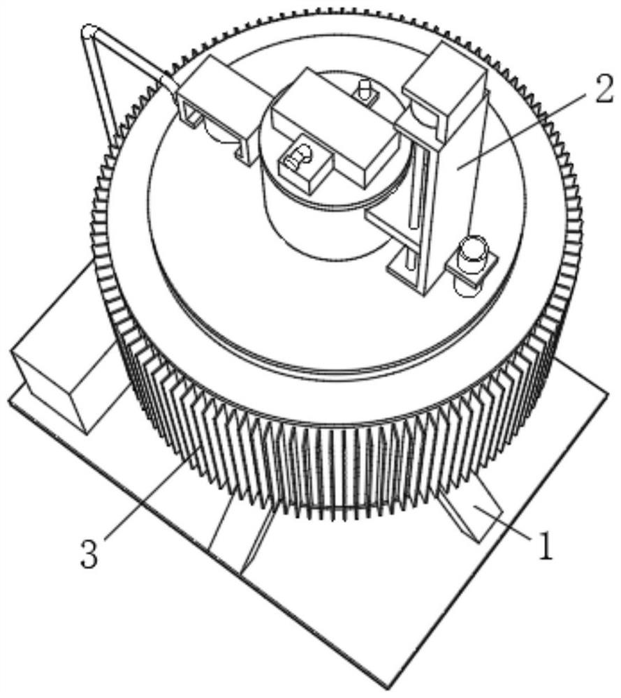
[0036] Such as Figure 1-10 As shown, the present invention provides a kind of rapid cooling device for chemical production, a material storage mechanism 1, a first cooling mechanism 2 and a second cooling mechanism 3 are fixed on the material storage mechanism 1, and the first cooling mechanism 2 is located at the front of the material storage mechanism 1. above;

[0037] The material storage mechanism 1 includes a material storage tank 4. A cover plate 5 is fixed on the top of the material storage tank 4. A first chute 6 is opened at the axis of the cover plate 5. A feed pipe 7 is fixed through the cover plate 5. The first slide Both the tank 6 and the feed pipe 7 are connected to the inside of the storage tank 4, and the bottom of the storage tank 4 is fixed with a discharge pipe 8, and the feed pipe 7 and the discharge pipe 8 are provided with a first valve 9, and the storage The bottom of the tank 4 is fixed with four support plates 10 distributed in a circular array, an...

Embodiment 2

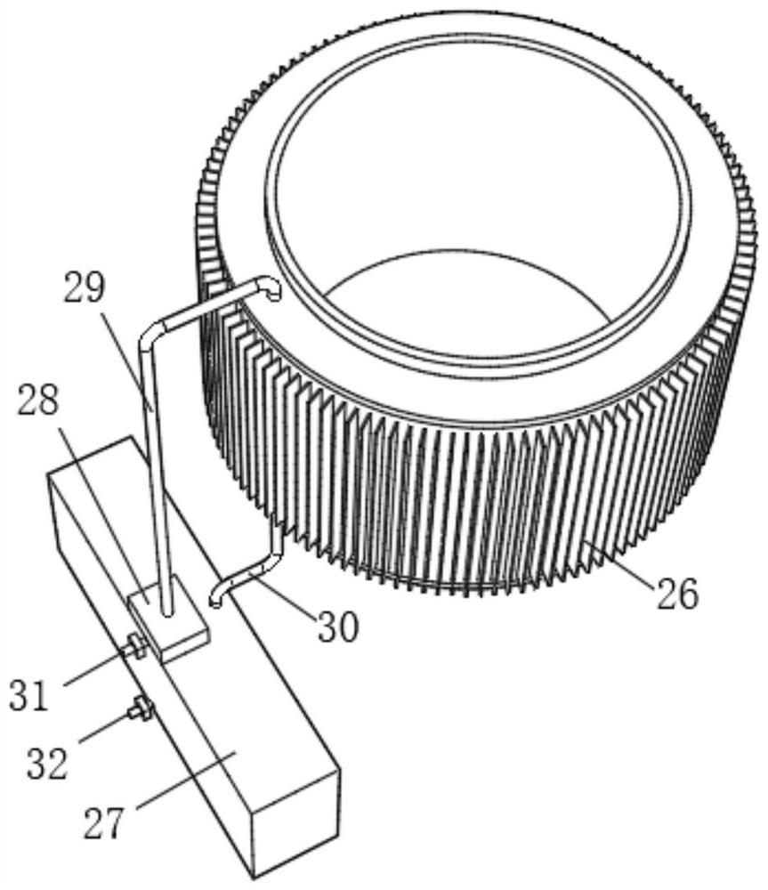
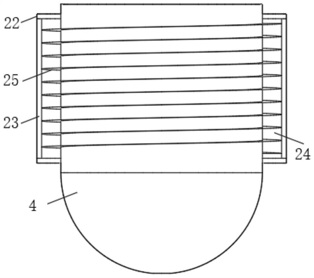
[0052] The applicant found in use that according to the operation process of Example 1, the cooling effect of the chemicals located above the fixed plate 15 is better, but the stirring effect of the chemicals located below the fixed plate 15 is relatively poor. For further cooling of chemical products, the applicant is provided with a number of baffles 48 on the inner wall of the storage tank 4 under the fixed plate 15. The baffles 48 are located opposite each other and staggered up and down. The baffles 48 are provided with cavities and It communicates with the cavity 24. When the operator controls the water pump 28 to input the water in the water tank 27 into the cavity 24, since the cavity in the baffle 48 communicates with the cavity 24, the water will flow into the baffle from the cavity 24 In the cavity in 48, the cooling area to the chemical products below the fixed plate 15 is increased, and the chemical products below the storage tank 4 are further cooled. Under the ac...


PUM


Abstract

The invention belongs to the technical field of chemical production, and discloses a rapid cooling device for chemical production. The rapid cooling device for chemical production comprises a storage mechanism, a first cooling mechanism and a second cooling mechanism. According to the rapid cooling device for chemical production, through mutual cooperation of the first cooling mechanism and the second cooling mechanism, chemicals carried in a storage tank can be subjected to internal and external synchronous cooling treatment; cooled compressed air is evenly dispersed in the storage tank in a bubble shape from the inner part of a cooling cylinder through small holes in stirring rods, so that the heat exchange area of the compressed air and the chemicals is increased, rapid cooling of the chemicals is achieved; a baffle plate with a cavity is arranged below a fixing plate, and the rapid cooling of the chemicals at the position without the stirring rods below the fixing plate is achieved, so that the time consumed for cooling the chemicals is greatly shortened, the heat exchange effect of the chemicals is better, and the production quality is improved.

Description

technical field [0001] The invention belongs to the technical field of chemical production, in particular to a rapid cooling device for chemical production. Background technique [0002] Chemical industry is the abbreviation of "chemical technology", "chemical industry", "chemical engineering", etc. Any technology that uses chemical methods to change the composition and structure of substances or synthesize new substances belongs to chemical production technology, that is, chemical technology. Known as chemicals or chemical products, the chemical industry includes petrochemicals, agricultural chemicals, chemical medicines, polymers, coatings, oils, etc. They appeared in different historical periods and have different meanings, but they are closely related, interpenetrating, and have a continuous In the process of its development, it was endowed with new content. The early life of human beings relied more on the direct use of natural materials. Gradually, the inherent propert...

Claims


Application Information

Patent Timeline
IPC IPC(8): F28C3/12F28F13/12
CPCF28C3/12F28F13/125
Inventor 蒋广
Owner 蒋广
Why Eureka
Try Eureka