A boat hull with a lateral thruster

A technology of propellers and hulls, applied in the field of hulls with lateral propellers, can solve problems such as affecting the sailing speed, driving the boat, and reducing the fuel consumption rate.

Active Publication Date: 2010-05-26
SUMITOMO CORPORATION +1
View PDF7 Cites 13 Cited by
  • Summary
  • Abstract
  • Description
  • Claims
  • Application Information

AI Technical Summary

Problems solved by technology

[0003] The channel of the lateral thruster is located in the water under the draft of the hull, and the opening (inlet and outlet) of the channel for

Method used


Image

  • A boat hull with a lateral thruster
  • A boat hull with a lateral thruster
  • A boat hull with a lateral thruster

Examples


Embodiment Construction

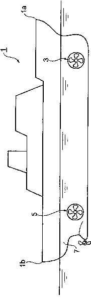
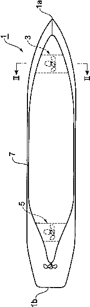
[0025] Hereinafter, preferred embodiments of the hull with side thrusters of the present invention will be described with reference to the drawings. Figure 1A with Figure 1B is a diagram briefly showing a hull (hereinafter, referred to as a "hull") 1 with side thrusters, where Figure 1A is the side view, Figure 1B It is a bottom view.

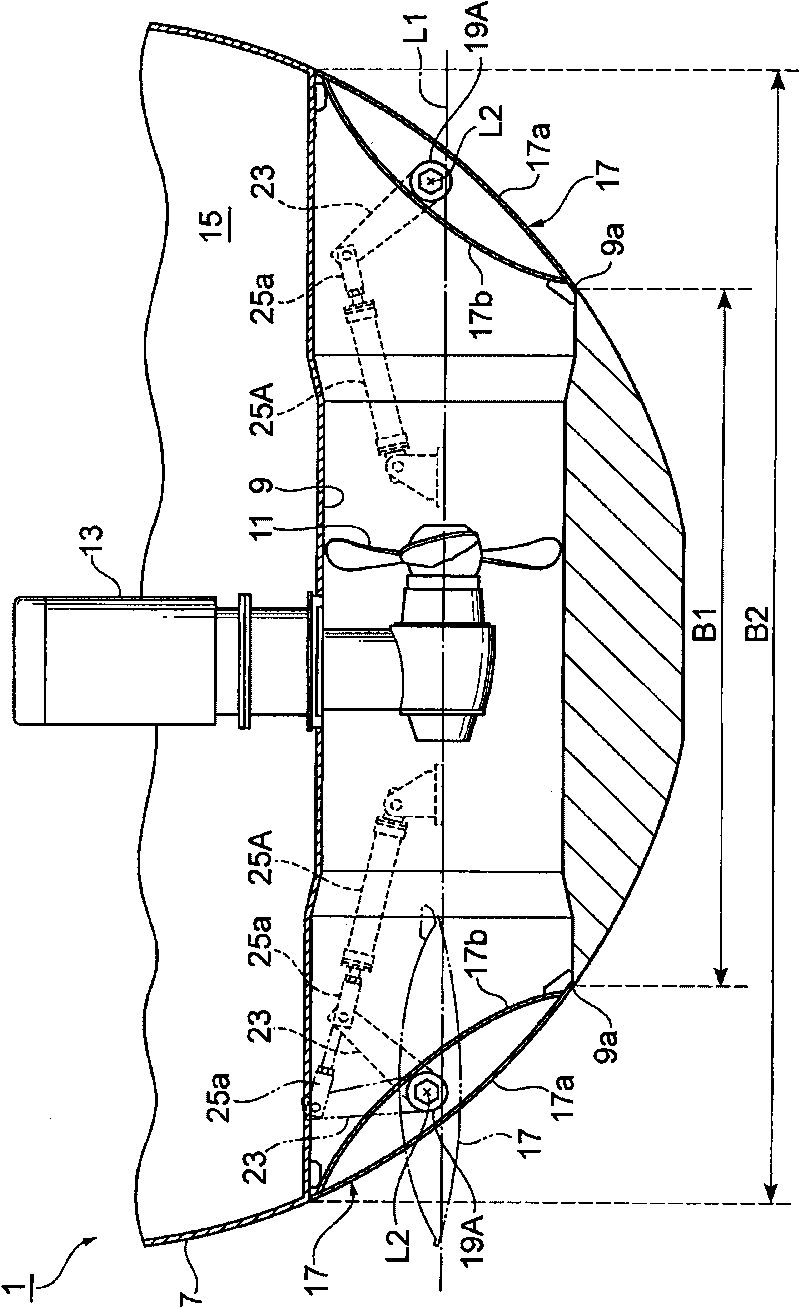
[0026] In the hull 1, the side thrusters 3 and 5 are provided in two parts, the front part on the bow 1a side and the rear part on the stern 1b side. The side thruster 3 on the bow 1 a side is generally called a bow thruster 3 , and the side thruster 5 on the stern 1 b side is usually called a stern thruster 5 . In recent years, some ships such as large passenger ships have three bow thrusters 3 and three stern thrusters 5 , but in this embodiment, a hull 1 including one bow thruster 3 and one stern thruster 5 is exemplified. If the bow thruster 3 and the stern thruster 5 are provided, the ship can be easily steered without calling a tugb...


PUM


Abstract

The invention provides a boat hull with a lateral thruster, which comprises the following components: a cover (17) of a passage (9) of a lateral thruster (3) that can be opened and closed; a shaft (19A) fixed on the cover (17) that supported by a boat bottom (7) and can rotate freely; and a drive apparatus (24) that open and close the cover (17) through the rotation of the shaft (19A), wherein, a rotational axis (L2) of the shaft (19A) extends along direction vertical to a passage axial cord (L1) of the passage (9), and departs from the passage axial cord (L1), and surface (17a) of the cover (17) when the passage (9) opened is closer to the passage axial cord (L1) compared to the time when a rotational axis (L2) crosses the passage axial cord (L1).

Description

technical field [0001] The invention relates to hulls with side thrusters. Background technique [0002] Conventionally, there is known a ship body provided with side thrusters in order to facilitate landing and departure of the ship body. The lateral thruster includes a passage running through the bottom of the ship transversely and a propeller arranged in the passage. Generally, lateral thrusters are respectively arranged on the bow side and the stern side to provide propulsion when the hull moves laterally. The hull with side thrusters improves maneuverability by eliminating the need for tugboats etc. when docking. [0003] The channel of the side thruster is located in the water under the draft of the hull, and the opening (port and exit) of the channel formed on the side of the hull constitutes resistance to sailing, affects sailing speed and steering, and reduces fuel consumption. Therefore, for example, a technology has been developed that provides a cover structur...

Claims


Application Information

Patent Timeline
IPC IPC(8): B63H5/07B63H23/26
CPCY02T70/12B63H25/42B63B1/32Y02T70/10B63B13/02
Inventor 野田福太郎
Owner SUMITOMO CORPORATION
Why Eureka
Try Eureka