Individually cooled turbocharger for no flow strategy in engine block coolant jacket

A technology of engine block and turbocharger, which is applied in the direction of engine cooling, coolant flow control, liquid cooling, etc., can solve the problems of expensive cast steel and heavy weight, and achieve light-weight manufacturing, rapid warm-up, The effect of reducing fuel consumption

Active Publication Date: 2011-12-07
FORD GLOBAL TECH LLC
View PDF7 Cites 16 Cited by
  • Summary
  • Abstract
  • Description
  • Claims
  • Application Information

AI Technical Summary

Problems solved by technology

However, cast steel is not only expensive but also has a relatively high weight, and any additional weight has a detrimental effect on the fuel consumption of motor vehicles as a whole

Method used


Image

  • Individually cooled turbocharger for no flow strategy in engine block coolant jacket
  • Individually cooled turbocharger for no flow strategy in engine block coolant jacket
  • Individually cooled turbocharger for no flow strategy in engine block coolant jacket

Examples


Embodiment Construction

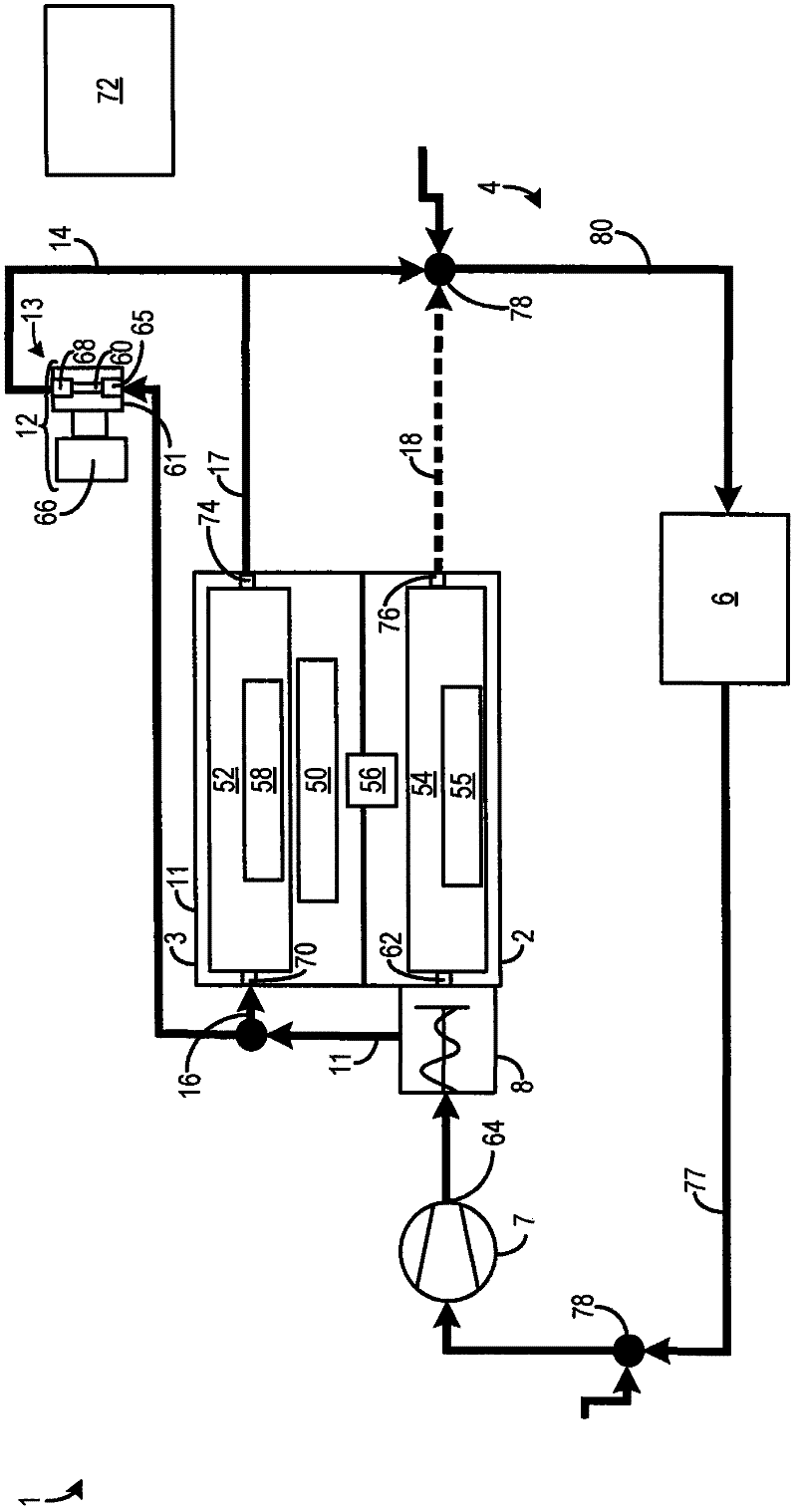
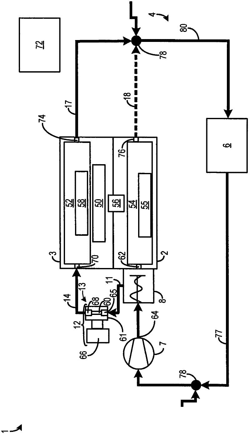
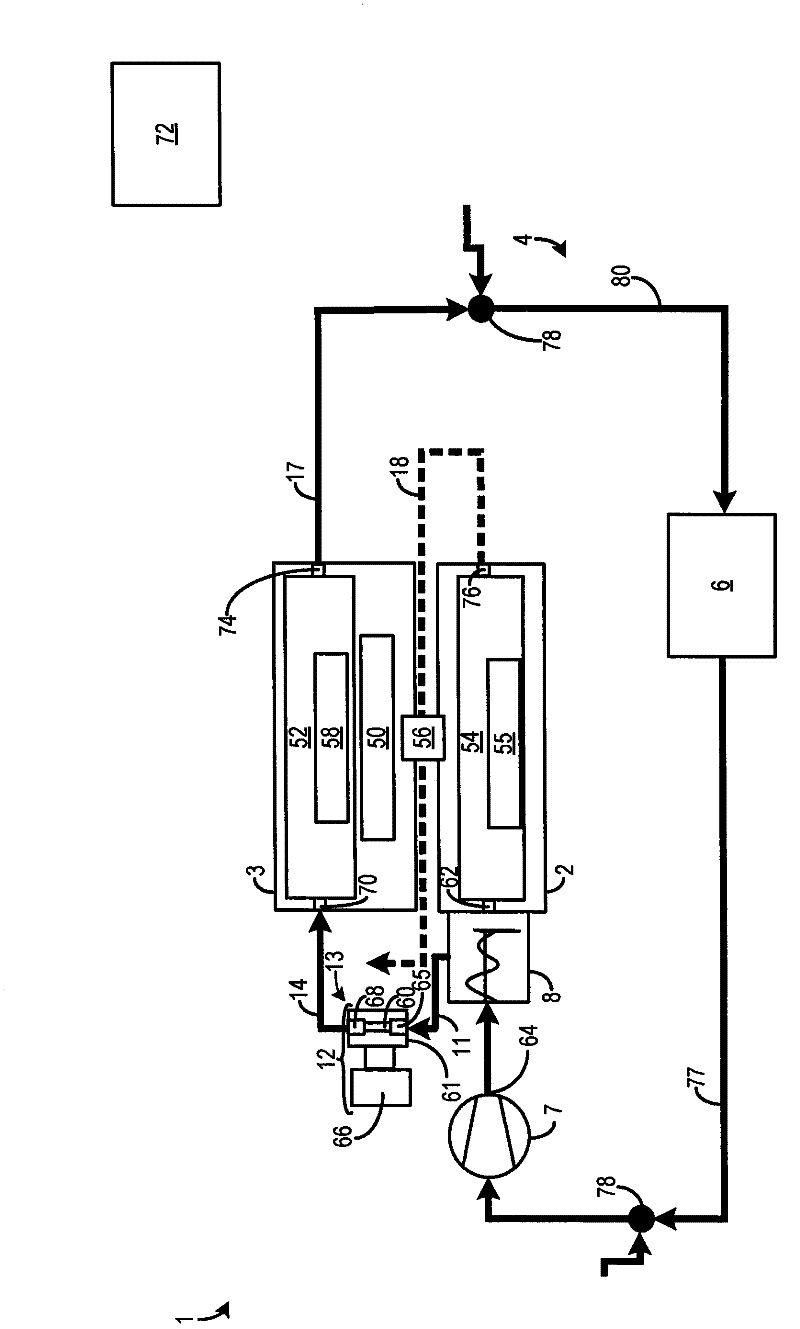
[0035] An internal combustion engine is described herein. The internal combustion engine includes a turbocharger with a turbine in the exhaust duct, the turbine having a turbine housing. The internal combustion engine further includes a cooling system comprising an engine block coolant jacket fluidly connected to the pump, a cylinder head coolant jacket fluidly connected to the pump, and a turbine coolant passage through the turbine housing and liquid Connects to the pump and bypasses the engine block coolant jacket. In some examples, a thermostat is positioned downstream of the pump and upstream of the engine block coolant jacket, cylinder head coolant jacket, and turbine coolant passages. The thermostat is configured to control the flow of coolant into the engine block coolant jacket, cylinder head coolant jacket and / or turbine coolant passages based on coolant and / or engine temperature.

[0036] A variety of cooling flow control strategies can be used in cooling systems. ...


PUM


Abstract

The engine (1) has a cylinder block coolant jacket operated in a turbine housing (13) in a turbocharger (12) during a subphase of a heating phase of the engine according to nitrogen oxide flow strategy. A cooling circuit (4) is separated from the cylinder block coolant jacket and connected with a common pump (7) that is joined to the cylinder block coolant jacket. A bypass (11) is provided downstream to the pump and upstream to a cylinder block coolant inlet (9). The housing is made of light material i.e. aluminum, where the housing or the turbocharger is provided with the cooling circuit. An independent claim is also included for a method for controlling coolant during a heating phase of an internal combustion engine.

Description

technical field [0001] The invention relates to an internal combustion engine having an engine block coolant jacket and a cylinder head coolant jacket, and having a turbocharger arranged with its turbine in an exhaust passage. Background technique [0002] Engine block coolant jackets and cylinder head coolant jackets have been developed to remove heat from the engine to improve engine operation. For example, EP 0 038 556 B1 describes a cooling system for an internal combustion engine. By means of a first pump, coolant is conveyed through the cylinder head coolant jacket. A second pump sends coolant through the block coolant jacket. Although the two coolant jackets have no connection in the internal combustion engine, both are open on the outlet side of the main circuit piping system. Branching off from the main circuit piping is a cooler bypass system that leads to the cylinder head inlet of the cylinder head coolant jacket and to the cylinder block inlet of the cylinder...

Claims


Application Information

Patent Timeline
Patent Type & Authority Applications(China)
IPC IPC(8): F01P3/00F01P3/12F01P3/02F01D25/14F02G5/02
CPCF01P7/165F01P2060/12F01P2003/027F01P2060/16F02B39/005
Inventor K·库荷尔巴茨B·施泰纳J·梅林
Owner FORD GLOBAL TECH LLC
Why Eureka
Try Eureka