Method and apparatus for manufacturing vitreous silica crucible and vitreous silica crucible
一种石英玻璃坩埚、制造方法的技术,应用在玻璃制造设备、玻璃的成型、制造工具等方向,达到防止过剩的加热、增大输出、增多电极根数的效果
- Summary
- Abstract
- Description
- Claims
- Application Information
AI Technical Summary
Problems solved by technology
Method used
Image
Examples
Embodiment 1
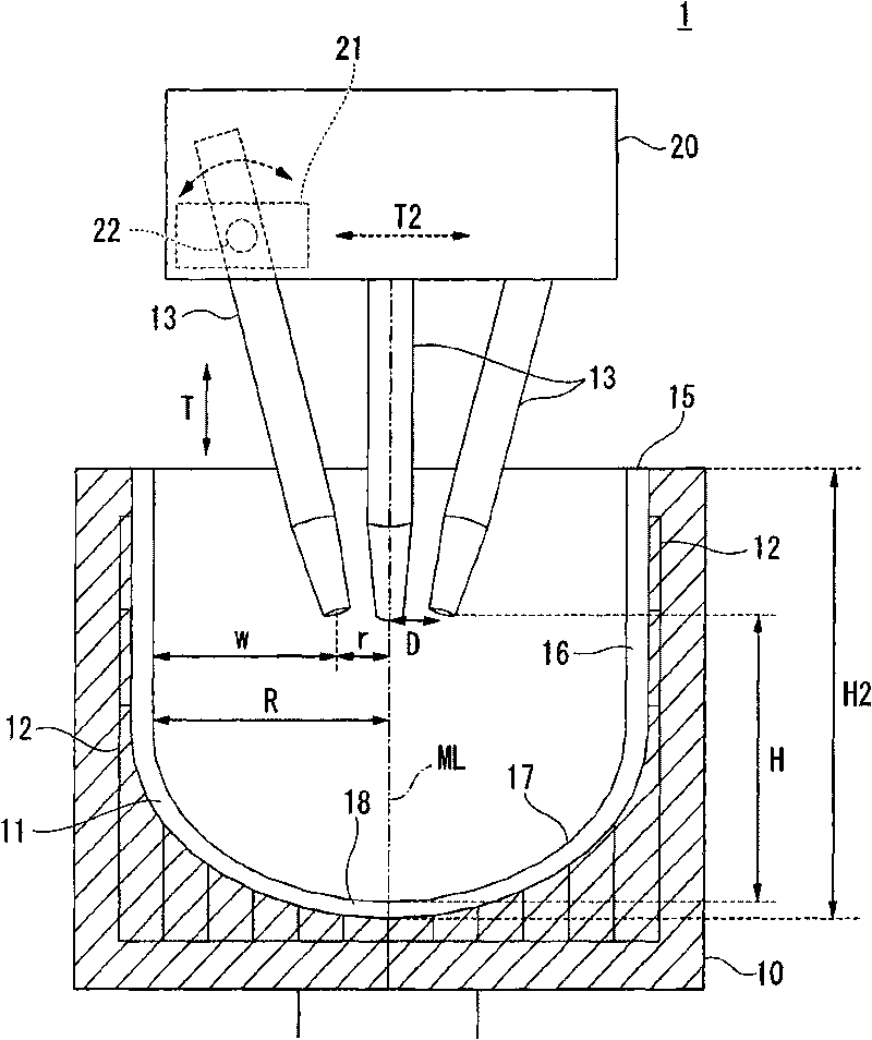
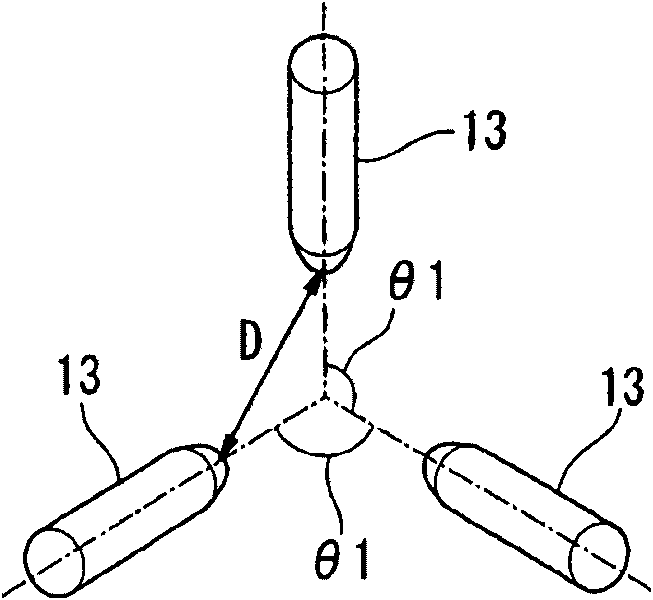
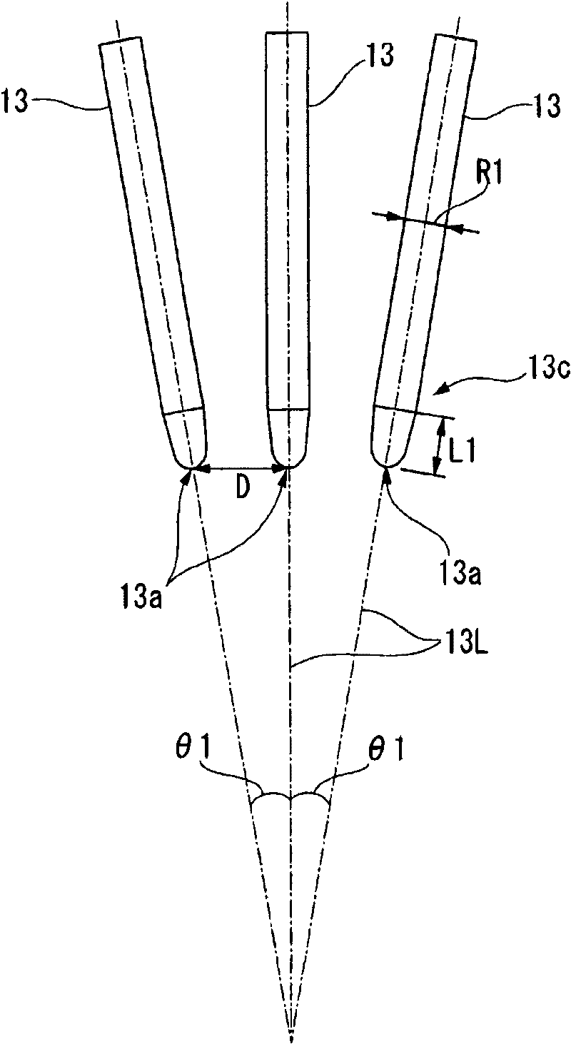
[0138] [Example 1] According to the rotational molding method, the quartz powder formed from the outer peripheral layer of the crucible to the inner peripheral layer was pre-stacked in the rotary mold, and the three-phase AC 6 electrodes of the present invention were used, and the existing three-phase AC 3 electrodes (Comparative Example 1) and 6-phase AC 6 electrodes (Comparative Example 2) each electrode structure, the distance between the electrodes was changed, the quartz powder was heated and melted, and a 32-inch quartz glass crucible was manufactured. The results are shown in Table 1. In the electrode structure of Comparative Example 1, when the expansion degree of the electrode, that is, the circumferential diameter of the disposed electrode is 81 mm, arc disconnection occurs frequently, and when the expansion degree of the electrode becomes larger than this, the arc cannot be generated. In addition, in the electrode structure of Comparative Example 2, although the exte...
Embodiment 2
[0142] [Example 2] In the manufacture of a vitreous silica crucible based on the rotational molding method, a vitreous silica crucible with a diameter of 32 inches used the 3-phase AC 6 electrodes of the present invention (Example) and the existing 6-phase AC In the electrode structure of 6 electrodes (Comparative Example 2) (the diameter of the circumference of the electrode is 243 mm), the electric power of 1000 KW was energized for 20 minutes, and the arc was generated 5 times, and the stability of the arc was investigated. The results are shown in Table 2. In the electrode structure of the present embodiment, the arc is stable, and even if the electric energy used in each time is approximately constant, in Comparative Example 2, the electric energy used in each time fluctuates greatly because the arc is unstable.
[0143] [Table 2]
[0144] Number of arcs
[0145] Number of arcs
Embodiment 3
[0146] [Example 3] In the manufacture of a quartz glass crucible based on the rotational molding method, for crucibles with a diameter of 22 to 40 inches, the 3-phase AC 6 electrodes of the present invention were used, and the conventional 3-phase AC 3 electrodes ( In Comparative Example 1), each electrode structure of 6-phase AC 6 electrodes (Comparative Example 2), the distance between the electrodes was changed, and electric power of 1000 kW was applied to generate an arc, and the stability was investigated. The results are shown in Table 3.
[0147] [table 3]
[0148] Crucible diameter
[0149] (Note) The diameter of the circumference is the diameter of the circumference where the electrode is placed, and it is 1 / 4 of the crucible hole diameter.
PUM
| Property | Measurement | Unit |
|---|---|---|
| diameter | aaaaa | aaaaa |
| diameter | aaaaa | aaaaa |
Abstract
Description
Claims
Application Information
 - R&D
- Intellectual Property
- Life Sciences
- Materials
- Tech Scout
- Unparalleled Data Quality
- Higher Quality Content
- 60% Fewer Hallucinations
Browse by: Latest US Patents, China's latest patents, Technical Efficacy Thesaurus, Application Domain, Technology Topic, Popular Technical Reports.
© 2025 PatSnap. All rights reserved.Legal|Privacy policy|Modern Slavery Act Transparency Statement|Sitemap|About US| Contact US: help@patsnap.com


