Open end rotor spinning device

A rotor spinning, free-end technology, which is applied to open-end spinning machines, spinning machines, and continuously wound spinning machines, etc., can solve the problems of complex structural design, difficult manipulation, and large structural space, and achieve improved textiles. Physical values, compact effects

Active Publication Date: 2013-03-27
SAURER GERMANY GMBH & CO KG
View PDF7 Cites 0 Cited by
  • Summary
  • Abstract
  • Description
  • Claims
  • Application Information

AI Technical Summary

Problems solved by technology

[0013] For the device according to DE 10 2004 017 700 A1, although different yarn batches can be spun with good weaving / physical values, this known device is very complicated in its structural design and somewhat bulky, rather important The reason is that a large construction space is required, especially when the opening roller housing is pivoted to a maximum extent
In other words, the device described in DE 10 2004 017 700 A1 proves to be difficult to maneuver when space is very limited in the workstation area of ​​an open-end rotor spinning machine

Method used


Image

  • Open end rotor spinning device
  • Open end rotor spinning device
  • Open end rotor spinning device

Examples


Embodiment Construction

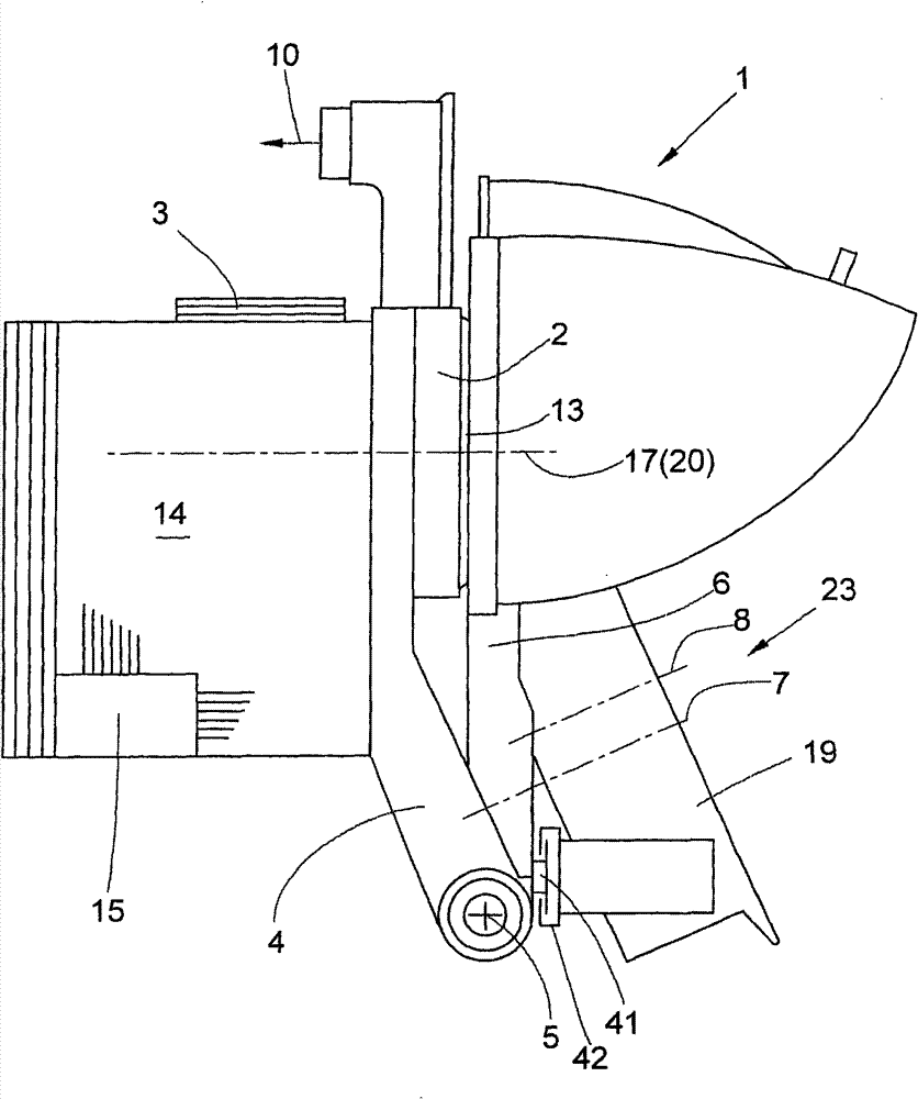
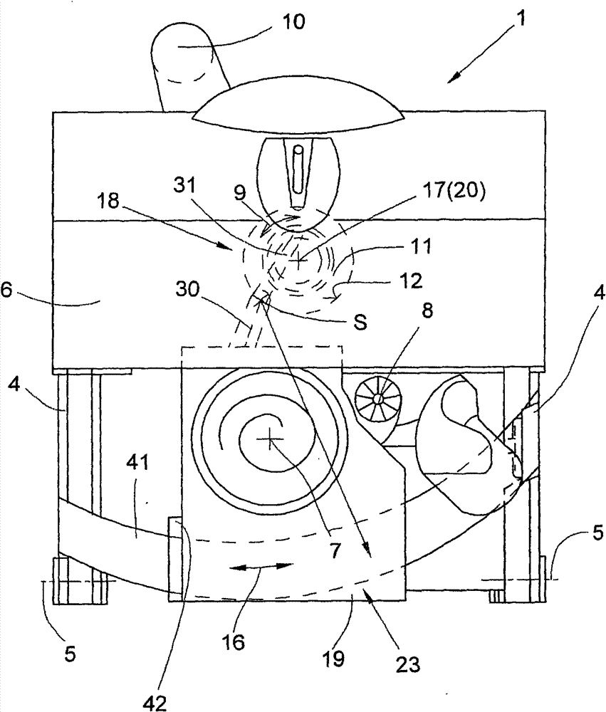
[0040] figure 1 An open-end rotor spinning device 1 is shown, the individual rotatably mounted functional elements of which can each be driven by a separate motor. An open-end rotor spinning device 1 of the type described, for example, in DE 103 40 657 A1 generally has a separate drive for the spinning rotor, a separate drive for the opening rollers and a separate drive for the sliver feed drum.

[0041] exist figure 1 The central spinning rotor, the opening rollers and the sliver feed cylinder are only shown schematically with their axes of rotation 17 , 7 and 8 , respectively. The spinning rotor, supported in magnetic bearings (not shown) and electromagnetically driven by a separate drive 3, rotates at high rotational speeds within the rotor housing 2, which can be subjected to negative pressure, during the spinning operation.

[0042] The rotor housing 2 is usually connected via a pneumatic line 10 to a source of negative pressure (not shown), away from the separate drive...


PUM


Abstract

The device (1) has a two-piece fiber guidance channel with an output channel section integrated into a channel disk adapter. An input-side channel section is arranged in a releasable roller housing (19), which is pivotably mounted in a limited manner. The channel disk adapter is pivotably mounted relative to a center axis (20) in a limited manner. The channel disk adapter is positioned independent of size of a tower-like attachment piece. Central longitudinal lines of the channel sections of the fiber guidance channel are arranged in an angle position to each other.

Description

technical field [0001] The invention relates to an open-end rotor spinning device. Background technique [0002] Open-end rotor spinning devices with a two-part yarn guide channel are known and described in great detail in numerous patent documents (eg DE 198 36 066 A1 or DE 198 41 406 A1). [0003] In a yarn guide channel constructed in this way, the outlet-side channel part is preferably integrated in a plate-shaped channel adapter, which in turn is arranged exchangeably in a corresponding receptacle of the cover element middle. During the spinning operation, the plate-shaped channel adapter, which is positioned precisely in the receptacle of the cover element, has a tower-shaped protrusion (the tower-shaped protrusion is separated from the mouth of the yarn-guiding channel and also has a function for fixing the yarn suction). The continuous central hole of the mouth) extends into the rotating spinning rotor. [0004] The cover element has a bearing bracket for the open...

Claims


Application Information

Patent Timeline
Patent Type & Authority Patents(China)
IPC IPC(8): D01H4/38
CPCD01H4/08D01H4/38
Inventor 海因茨-格奥尔格·瓦森霍芬
Owner SAURER GERMANY GMBH & CO KG
Why Eureka
Try Eureka