Fuel conveying method and equipment of boiler for burning crop straws

A technology for fuel transportation and crops, applied in the combustion method, combustion equipment, fuel supply and other directions, can solve the problems of arched feeding device, high processing cost, poor feeding, etc., achieve stable and reliable operation, reduce processing cost, reduce Effects of processing costs

Active Publication Date: 2012-04-25
CHINA LIGHT IND NANNING DESIGN ENG
View PDF8 Cites 0 Cited by
  • Summary
  • Abstract
  • Description
  • Claims
  • Application Information

AI Technical Summary

Problems solved by technology

At present, there are mainly several fuel pretreatment and delivery methods for boilers burning crop straws at home and abroad: one method is to use the conventional coal delivery system to put the crushed and granulated straw pellets into the boiler for combustion through the conveyor belt. The pretreatment method has high processing costs due to the complexity of the pellet forming process; one method is to use a specific feeding device, such as a propulsion feeding device, a screw feeding device for fuel delivery, but this type of feeding device has a high impact on the fuel. Strict size requirements, only for narrow screening, single-scale, small-size granular materials, and even if such materials are used, in actual operation, there are often "overlapping" and "arching" in the silo and improper feeding of the feeding device. Chang and other problems; one method is to chop strips of crop straw into 10-200mm strips and then feed them into the feeding device, but the strips after chopping have low bulk density and large size Different, complex shapes, interlaced and other characteristics, often appear "bridge" and "arch" phenomenon in the silo, unable to enter the feeding device smoothly
In addition, when the existing conventional feeding device transports this type of crop straw, there will be problems such as blockage or even damage to the equipment

Method used


Image

  • Fuel conveying method and equipment of boiler for burning crop straws
  • Fuel conveying method and equipment of boiler for burning crop straws
  • Fuel conveying method and equipment of boiler for burning crop straws

Examples


Embodiment Construction

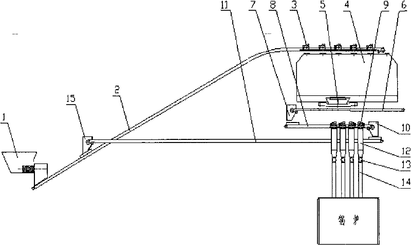
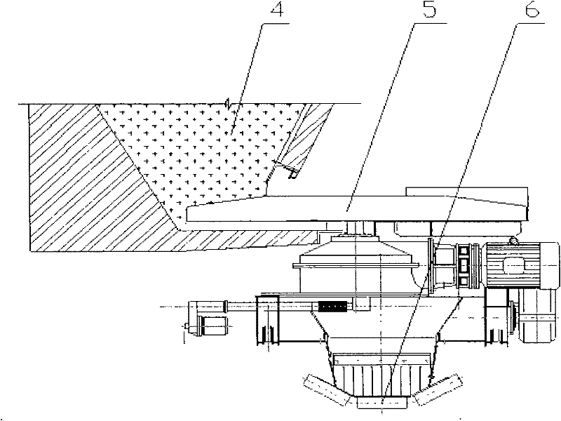
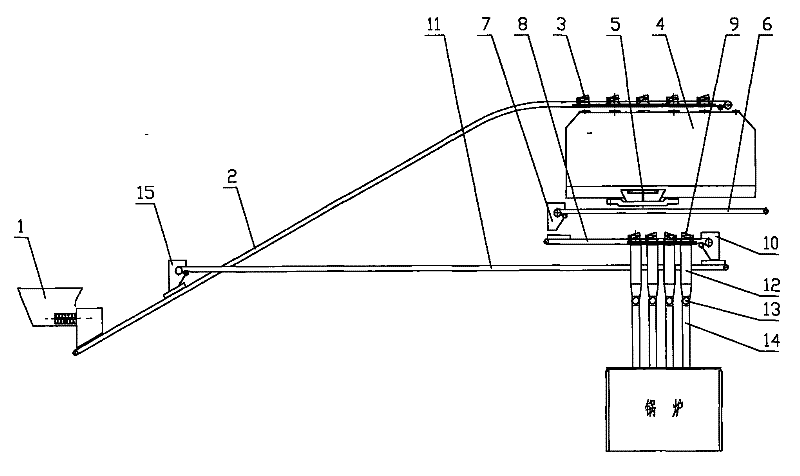
[0016] The fuel delivery method and equipment of the boiler burning crops and orange stalks of the present invention use the movable impeller feeding trolley and the drum feeder to change the feeding mode of the silo and the feeding mode of the boiler, reduce the operating cost, and realize uniform and stable feeding. and reduce equipment damage. The fuel delivery device of the present invention is mainly composed of a hopper 4, a mobile impeller feeding trolley 5, an upper-level feeding pipe 12, a drum feeder 13, and a lower-level feeding pipe 14. The crushed and pretreated crop straw fragments with a size of 5-25mm or larger are sent to the silo 4, and are fed through the movable impeller feeding trolley 5 at the bottom, and the straw fragments coming out of the movable impeller feeding trolley can be It directly falls into the upper-level feeding pipe 12, and then the crop orange stalk fuel is transported into the boiler through the lower-level feeding pipe 14 of the drum f...


PUM


Abstract

The invention relates to a fuel conveying method of a boiler for burning crop straws. By utilizing a method of relative moving and rolling of materials during feeding in a burner, the materials of a feed inlet are moved and rolled through a moving type impeller feeding device and a roller type feeder and then reenter the burner. The method can reduce the operation cost, realize uniform and stable feeding and reduce equipment damages. Equipment designed by the method mainly comprises a material cabin, a moving type impeller feeding trolley, an upper blanking pipe, the roller type feeder and a lower blanking pipe. Fragmental crop straw materials pretreated by smashing in a size of 5-25mm or a larger size are sent into the material cabin, and the moving type impeller feeding trolley at the bottom of the material cabin is used for feeding the materials; straw fragmental materials coming out of the moving type impeller feeding trolley fall on the upper blanking pipe; and then crop straw fuels are sent into a boiler through the lower blanking pipe of the roller type feeder.

Description

technical field [0001] The invention relates to a fuel delivery method and equipment for a boiler that burns crops and orange stalks, and belongs to a fuel delivery method and equipment at a burner inlet. technical background [0002] Crop straw is a by-product of agricultural production with large output and wide distribution. It is an environmentally friendly, clean and renewable biomass energy. Clean and efficient use of crop straw to produce biomass energy is an important energy strategy in the world. At present, combustion technology is an important technology for utilizing crop straw. This technology can convert this low-quality energy into high-quality energy, and has significant economic, social and environmental benefits. [0003] In the industrial application of crop straw combustion technology, especially in boiler combustion applications, continuous and stable feeding is very important. At present, there are mainly several fuel pretreatment and delivery methods...

Claims


Application Information

Patent Timeline
Patent Type & Authority Patents(China)
IPC IPC(8): F23K3/00
Inventor 梁辉仪阮友文刘萍劳运剑
Owner CHINA LIGHT IND NANNING DESIGN ENG
Why Eureka
Try Eureka