An air conditioner
A technology for air conditioners and cabinets, applied to mechanical equipment, space heating and ventilation, heating methods, etc., can solve problems such as increased development costs, user anxiety, and inability to confirm, so as to improve energy saving or satisfaction, and achieve comfort , the effect of maintaining comfort
- Summary
- Abstract
- Description
- Claims
- Application Information
AI Technical Summary
Problems solved by technology
Method used
Image
Examples
Embodiment 1
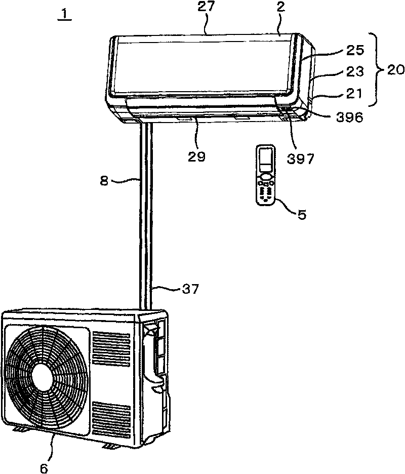
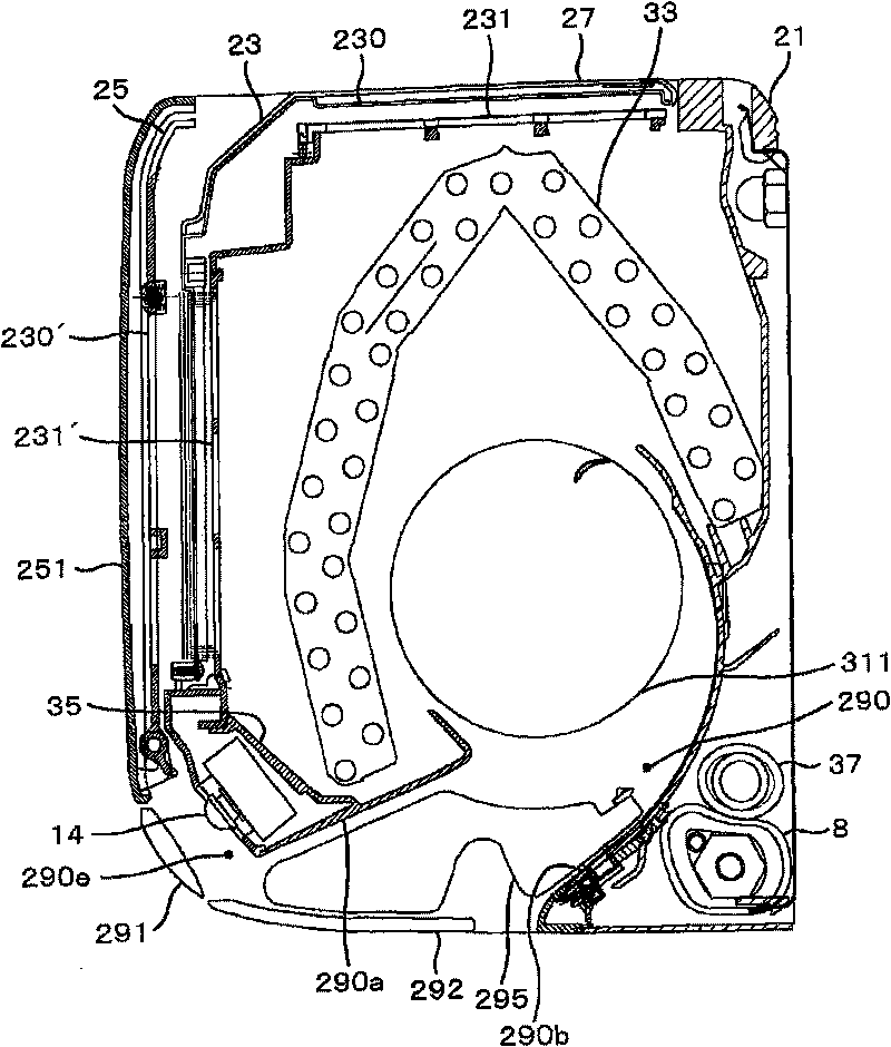
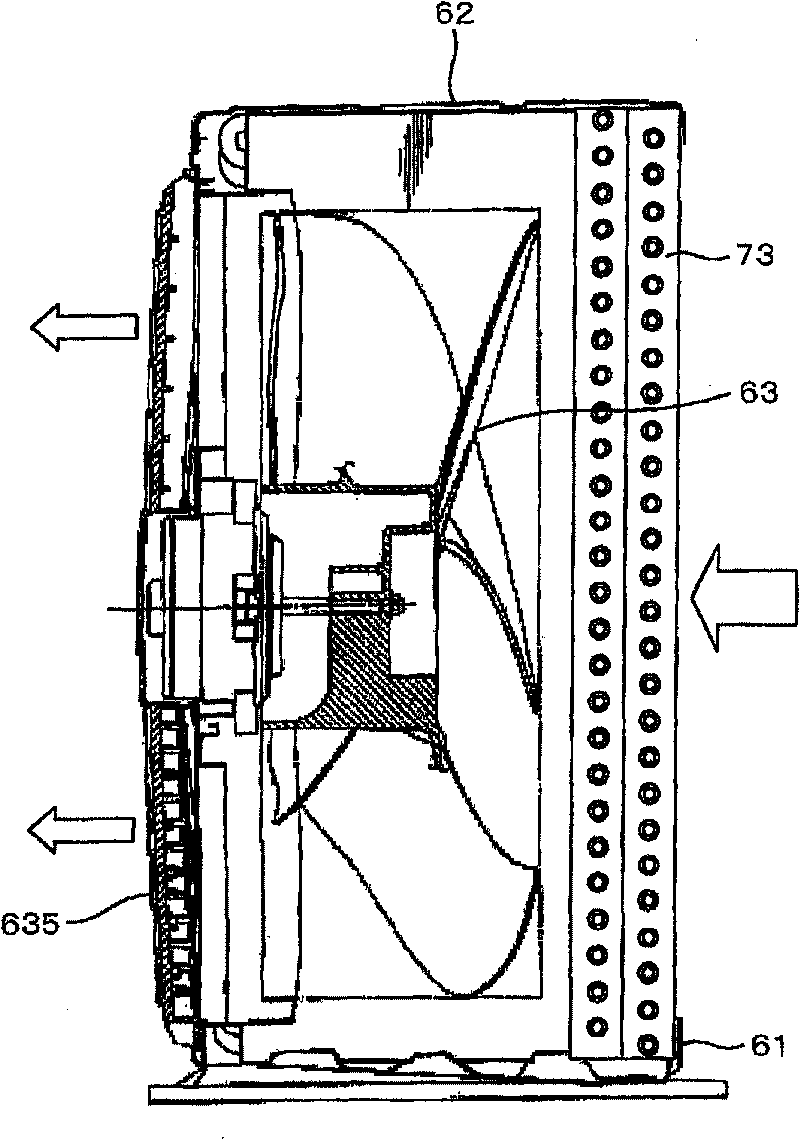
[0100] First, use Figure 1 ~ Figure 4 The overall structure of the air conditioner will be described. figure 1 It is a block diagram of the air conditioner of an Example. figure 2 It is a sectional view of the indoor unit of the air conditioner. image 3 It is a sectional view of the outdoor unit of the air conditioner. Figure 4 It is a refrigerant circuit diagram of the air conditioner, (a) is a diagram showing the flow direction of the refrigerant during the cooling and dehumidification operation, and (b) is a diagram showing the flow direction of the refrigerant during the heating operation.
[0101] The connecting pipe 8 for the air conditioner connects the indoor unit 2 and the outdoor unit 6 to perform air conditioning in the room. In the indoor unit 2, an indoor heat exchanger 33 is arranged in the central part of the chassis base 21, and an indoor ventilation fan 311 of a cross-flow fan type with a length approximately equal to the width of the heat exchanger 33 ...
Embodiment 2
[0298] Next, use Figure 48 ~ Figure 50 Example 2 in which the number of infrared sensors is increased will be described. Figure 48 It is a detection range diagram of the infrared detection device of Example 2. Figure 49 It is the detection area division diagram of the detection device. Figure 50 It is the estimation map of the existence area of the detection device, (a) is a schematic diagram of area division, (b) is the existence area when the difference between a and b is large, and (c) is the existence area when the difference between a and b is small .
[0299] Example 2 as Figure 48 As shown, the number of infrared sensors 410 in Embodiment 1 is increased from 2 to 3, and arranged as adjacent left person detection sensor 140a and middle person detection sensor 140b and middle person detection sensor 140b and right person detection sensor 140c The detection ranges of the left person detection sensor 140a and the right person detection sensor 140c at both ends do n...
Embodiment 3
[0309] Next, use Figure 51 ~ Figure 53 Example 3 in which the arrangement of three infrared sensors is changed will be described. Figure 51 It is a schematic diagram of the detection area of the infrared detection device of Example 3. Figure 52 It is the detection area division diagram of the detection device. Figure 53 It is the estimation map of the existence area of the detection device, (a) is a schematic diagram of area division, (b) is the existence area when the difference between a and b is large, and (c) is the existence area when the difference between a and b is small .
[0310] Example 3 as Figure 51 As shown, the arrangement of the human detection sensors 140a-c in Embodiment 2 is changed, and the detection ranges of the adjacent left human detection sensor 140a and middle human detection sensor 140b and the middle human detection sensor 140b and right human detection sensor 140c are arranged. Some overlap, and the detection ranges of the left person ...
PUM
 Abstract
Description
Claims
Application Information
 - R&D
- Intellectual Property
- Life Sciences
- Materials
- Tech Scout
- Unparalleled Data Quality
- Higher Quality Content
- 60% Fewer Hallucinations
Browse by: Latest US Patents, China's latest patents, Technical Efficacy Thesaurus, Application Domain, Technology Topic, Popular Technical Reports.
© 2025 PatSnap. All rights reserved.Legal|Privacy policy|Modern Slavery Act Transparency Statement|Sitemap|About US| Contact US: help@patsnap.com


