System and device comprising a combined condenser and evaporator

A condenser and evaporator technology, applied in evaporator/condenser, transportation and packaging, refrigeration and liquefaction, etc., can solve the problems of no compressor system and its components, bulky and other problems

Active Publication Date: 2010-05-26
SCANIA CV AB
View PDF7 Cites 15 Cited by
  • Summary
  • Abstract
  • Description
  • Claims
  • Application Information

AI Technical Summary

Problems solved by technology

Nor has it been previously taught how to make compressor systems and their component parts less bulky, less expensive to manufacture, and easier to install

Method used


Image

  • System and device comprising a combined condenser and evaporator
  • System and device comprising a combined condenser and evaporator
  • System and device comprising a combined condenser and evaporator

Examples


Embodiment Construction

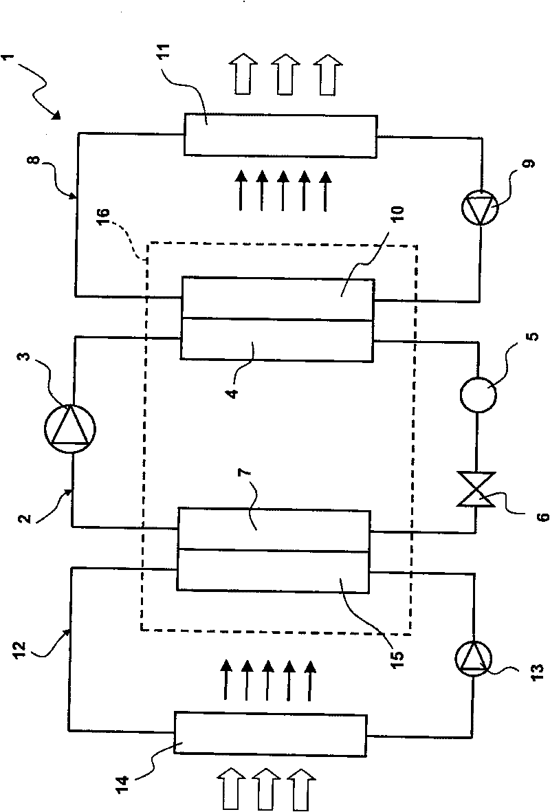
[0033] figure 1 A compressor system 1 according to the invention is shown. The compressor system 1 here comprises three different circuits. The first circuit, the main refrigerant circuit 2 , comprises a compressor 3 , a condenser 4 , a dry filter 5 , an expansion device 6 and an evaporator 7 . These elements are connected to each other through a pipeline system, and the entire circuit 2 is hermetically sealed, and contains and utilizes a refrigerant (such as CO 2 ) operate under pressure.

[0034] The expansion device 6 employs an adjustable expansion valve or a fixed constriction. In a compressor system using an expansion valve, it is important that the expansion valve is constantly supplied with fluid. Thus, the dry filter 5 is located upstream of the expansion valve 6 and has an outlet at the bottom of its container (not shown). This ensures that the expansion valve 6 is always supplied with fluid and thus operates correctly.

[0035] The second circuit 8 , the cooling...


PUM


Abstract

The invention relates to a system and a device for cooling and / or warming which comprises at least a refrigerant circuit (2) with at least a compressor (3), a condenser (4), an evaporator (7) and an expansion means (6). The invention is effected by the evaporator and the condenser being combined / integrated in a single common unit (16) which comprises an internal heat exchanger (19).

Description

technical field [0001] The present invention generally relates to a compressor system having a closed refrigerant circuit for cooling and / or heating purposes, the refrigerant circuit comprising at least a condenser and an evaporator. In particular the invention relates to a system and arrangement for cooling and / or heating the interior of a vehicle, in particular the cab / driving space of a commercial / heavy-duty vehicle with a tiltable cabin. More specifically, the invention relates to a compressor system comprising at least one additional auxiliary low pressure circuit for transferring heat and cold using water and / or glycol or other medium suitable for transferring heat and cold. Background technique [0002] As is known, air conditioning systems in motor vehicles generally include an air-cooled condenser located at or near the front of the vehicle, an evaporative condenser located at a location in the vehicle cabin, such as in or under the dashboard. devices, and the line...

Claims


Application Information

Patent Timeline
Patent Type & Authority Applications(China)
IPC IPC(8): F25B1/00F25B39/00F25B40/06F25B41/06B60H1/32
CPCF25B40/00F28D9/005B60H1/3227B60H1/00899F28D9/0093B60H2001/00957B60H2001/00928B60H1/00342B60H1/32284F25B39/00
Inventor O·哈尔
Owner SCANIA CV AB
Why Eureka
Try Eureka