Electroconductibility single-hole diluting method for detecting seepage speed

A technology of seepage velocity and conductivity, which is applied in fluid velocity measurement, velocity/acceleration/shock measurement, measuring devices, etc., and can solve problems such as prone to radioactive accidents

Active Publication Date: 2010-05-26
NANJING HYDRAULIC RES INST
View PDF0 Cites 20 Cited by
  • Summary
  • Abstract
  • Description
  • Claims
  • Application Information

AI Technical Summary

Problems solved by technology

[0008] The isotope single-well dilution test is a radioactive operation during the tracer injection process, and radioactive

Method used


Image

  • Electroconductibility single-hole diluting method for detecting seepage speed
  • Electroconductibility single-hole diluting method for detecting seepage speed
  • Electroconductibility single-hole diluting method for detecting seepage speed

Examples


Embodiment 1

[0062] The conductivity single-hole dilution method for measuring seepage velocity includes: selecting the position of the measuring hole and drilling the hole, selecting the tracer according to the different conductivity of the water body of the drilling hole on the spot, and measuring the relationship between the conductivity and the concentration of the tracer solution in the laboratory. The tracer solution is put into the hole, the conductivity of the water body in the hole is measured, and the seepage flow rate is calculated by using the change rate of the measured conductivity.

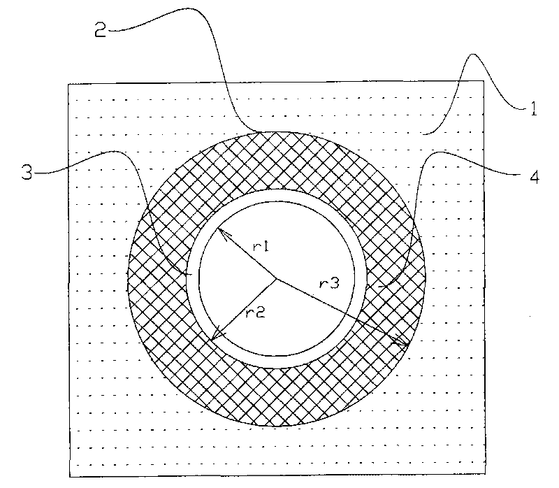
[0063] Select the geologically stable area to be measured, and drill holes at the position of no broken zone. The hole depth is below the estimated aquifer 1. The measuring hole 2 has a built-in filter tube 3; the filter tube 3 is equipped with a gravel layer 4, see figure 1 ;

[0064] The tracer was selected according to the different conductivity of the drilling water body on site, and the mea...

Embodiment 2

[0077] The conductivity single-hole dilution method for measuring seepage velocity includes: selecting the position of the measuring hole and drilling the hole, selecting the tracer according to the different conductivity of the water body of the drilling hole on the spot, and measuring the relationship between the conductivity and the concentration of the tracer solution in the laboratory. The tracer solution is put into the hole, the conductivity of the water body in the hole is measured, and the seepage flow rate is calculated by using the change rate of the measured conductivity.

[0078] In the area to be measured, select geologically stable, no broken zone to drill holes, the hole depth is below the estimated aquifer 1, and the measuring hole 2 has a built-in filter tube 3; the filter tube 3 has no gravel layer outside;

[0079] The tracer was selected according to the different conductivity of the drilling water body on site, and the measured conductivity of the drilling...

Embodiment 3

[0089] The conductivity single-hole dilution method for measuring seepage velocity includes: selecting the position of the measuring hole and drilling the hole, selecting the tracer according to the different conductivity of the water body of the drilling hole on the spot, and measuring the relationship between the conductivity and the concentration of the tracer solution in the laboratory. The tracer solution is put into the hole, the conductivity of the water body in the hole is measured, and the seepage flow rate is calculated by using the change rate of the measured conductivity.

[0090] In the area to be measured, select geologically stable, no broken zone to drill holes, the hole depth is below the estimated aquifer 1, and the measuring hole 2 has a built-in filter tube 3; the filter tube 3 has no gravel layer outside;

[0091] The tracer was selected according to the different conductivity of the drilling water body on site, and the measured conductivity of the drilling...


PUM

PropertyMeasurementUnit
Conductivityaaaaaaaaaa

Abstract

The invention relates to an electroconductibility single-hole diluting method for detecting seepage speed, which belongs to the field of seepage and underground water motion observation. The method comprises the following steps of: selecting a hole measurement position and drilling; selecting a tracing agent according to the difference of electroconductibility of scene drilling water; detecting arelation between the electroconductibility and the concentration of a tracing agent solution in a laboratory; filling the tracing agent solution into a hole; measuring the electroconductibility of the water in the drilled hole; and calculating the seepage speed by the variation rate of the measured electroconductibility. The method has simple, convenient and reliable operation, clear principle, simple, convenient and safe measurement process, accurate and reliable result, environmental protection and safety, selects the tracing agent from a nontoxic strong electrolyte solution or a deionized aqueous solution and can fully replace the traditional radioactive single-hole flow speed detecting method.

Description

technical field [0001] The invention discloses a conductivity single-hole dilution method for measuring seepage velocity, which relates to measuring groundwater movement by tracer dilution method, especially a method for calculating seepage flow velocity by measuring conductivity change, belonging to the field of seepage and groundwater movement observation. Background technique [0002] The principle of the tracer dilution method to measure the flow rate was first proposed by Kocherin. If the mixture is evenly mixed, the concentration of the tracer will continue to decrease with the water flow. The infiltration flow rate of the aquifer can be calculated by measuring the concentration of the tracer twice before and after the water column in this section. Later, the method was gradually improved by researchers such as Moser and Drost. [0003] In 1957, Moser proposed a radioactive single-hole dilution method to measure the groundwater seepage velocity, under the assumption t...

Claims


Application Information

Patent Timeline
IPC IPC(8): G01P5/08G01N27/06
Inventor 郭永彬沈杰程和森曹更新王守家魏明成
Owner NANJING HYDRAULIC RES INST
Why Eureka
Try Eureka