Electrical operating mechanism for switchgear

A technology of using electric operation and switching equipment, applied in the field of electric operation mechanism, can solve the problems such as the inability to meet the requirements of use, and achieve the effects of excellent transmission characteristics, small size and easy processing

Active Publication Date: 2010-05-26
西安西电高压开关操动机构有限责任公司 +1
View PDF1 Cites 26 Cited by
  • Summary
  • Abstract
  • Description
  • Claims
  • Application Information

AI Technical Summary

Benefits of technology

The technical effect described by this inventor's invention relates to improving the design of electrical equipment such as gas insulated metal enclosures or circuit breakers while reducing their overall dimensions without sacrificing functionality. It achieves these benefits through combining different types of transmission techniques like geartrain combination transmission devices and transferring them into one unit instead of multiple units. Additionally, there is a novel way to simplify the construction of the machine due to fewer components needed compared to previous designs. Overall, this technology allows for better control over power distribution systems and improved safety measures.

Problems solved by technology

In this patented technical problem addressed by this patents relates to improving the design of an electrical operation system where there exist various types of isolated switching devices such as gears and cams. However, current systems have limitations due to their mechanical structures and limited rotational range capabilities.

Method used


Image

  • Electrical operating mechanism for switchgear
  • Electrical operating mechanism for switchgear
  • Electrical operating mechanism for switchgear

Examples


Embodiment Construction

[0030] The present invention will be further described in detail below in conjunction with the accompanying drawings and specific embodiments.

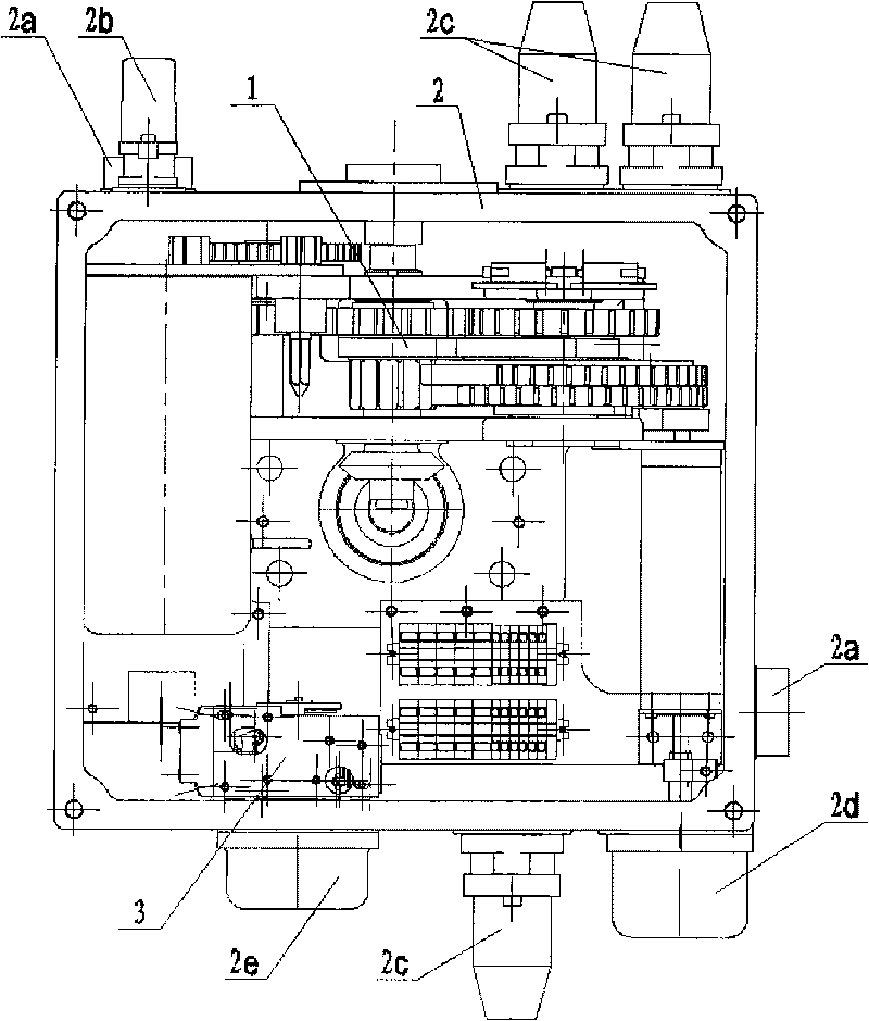
[0031] like figure 1As shown, the present invention is mainly made up of core 1, mechanism box 2 and manual operation interlocking device 3. The core 1 and manual operation interlocking device 3 are fixed in the mechanism box 2, and the mechanism box 2 is provided with a box Ventilation window 2a for internal and external ventilation, connectors 2b and 2c for leading and introducing electrical connection wires of the mechanism, opening and closing position indicator 2d, protective cover 2e for manual operation interlocking device.

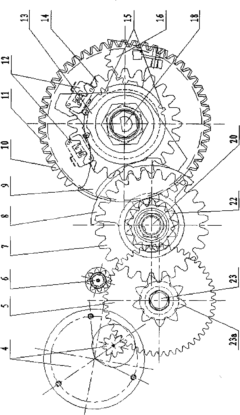
[0032] In this embodiment, the steering of the output shaft of the mechanism is counterclockwise for opening and clockwise for closing. like Figure 4 shown.

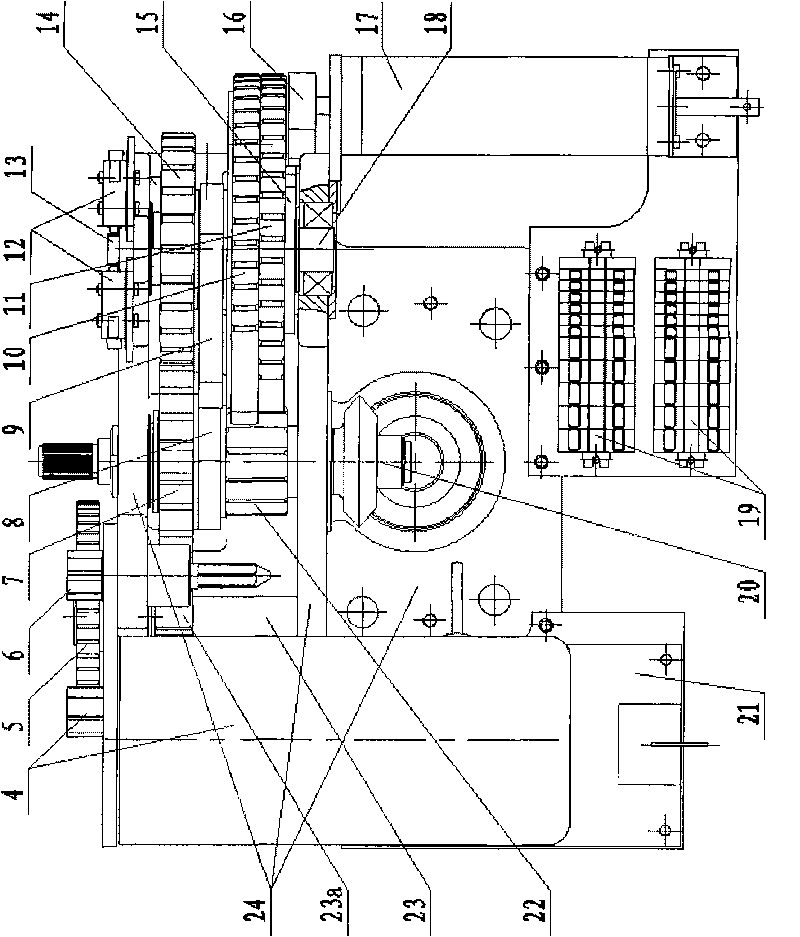
[0033] like figure 2 , image 3 As shown, the mechanism core part includes a cast aluminum mechanism bracket 24 on which a main shaft 18 , an...


PUM


Abstract

The invention discloses an electrical operating mechanism used in a gas insulated metal-enclosed switchgear (GIS). A special gear/cam combination drive and conversion mode is utilized to ensure that the output rotator angle of an original gear/cam combination driving device which can reach about 3/4 turns to the maximum is converted into an output rotator angle near three-turn, and the needs of multi-turn input required by an isolating switch and a grounding switch in the high-voltage (252-1100kV) GIS whole-set switchgear are satisfied. In the invention, a pair of auxiliary switches driven by the cam is adopted, the number of the transmission parts is reduced to the minimum limit, the auxiliary switch and a driving shaft of the auxiliary switch are enabled to approach very close, the size of the mechanism is decreased, the transmission and positioning are precise, the performance is reliable and the auxiliary switches can be very conveniently switched at any needed position through changing the positions of two teeth of the cam. The invention has the advantages of excellent transmission characteristics, little impact force of switching-in and switching-off startup and placing, high precision of the output rotator angle of the mechanism as well as exact and reliable positioning and maintenance of the switching-in and switching-off placing.

Description


Claims


Application Information

Patent Timeline
Owner 西安西电高压开关操动机构有限责任公司
Why Eureka
Try Eureka