
High-frequency induction heating device

A heating device and high-frequency induction technology, applied in heat treatment furnaces, heat treatment equipment, and energy efficiency improvement, can solve problems such as poor work efficiency, difficult quenching and annealing quality, and difficulty in ensuring workpieces, and achieve improved efficiency, good quenching or annealing. quality effect

Inactive Publication Date: 2010-06-02
宫电高周波设备(上海)有限公司
View PDF1 Cites 4 Cited by
  • Summary
  • Abstract
  • Description
  • Claims
  • Application Information

AI Technical Summary

Problems solved by technology

[0005] However, on such a high-frequency induction heating device, the conditions for quenching and annealing of the workpiece are different, and heating devices with high-frequency power supplies with different frequencies are used respectively. It is difficult to simply and continuously quench and anneal the workpiece, and the work efficiency is poor.
[0006] In addition, once the workpiece quenched by the quenching heating device is taken out from the heating device, it must be installed on the annealing heating device installed at another location for annealing. Therefore, when the workpiece is moved between the heating devices, quenching may occur. Defective workpieces or workpieces that have not been quenched are supplied to the heating device for annealing for annealing. In this way, it is difficult to ensure that the workpiece is quenched under the specified conditions and then annealed under the specified conditions, and it is also difficult to easily and stably heat the workpiece on the workpiece. to obtain good quenching and annealing quality

Method used


Image

  • High-frequency induction heating device
  • High-frequency induction heating device
  • High-frequency induction heating device

Examples


Embodiment Construction

[0022] Embodiments of the present description will be described in detail below based on the drawings.

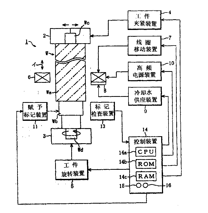
[0023] Figure 1 to Figure 6 One embodiment of the high-frequency induction heating device related to the present invention is shown. Such as figure 1 As shown, the high-frequency induction heating device 1 has the following components: an upper support member 2 and a lower support member 3 that support the upper and lower ends of a shaft-shaped workpiece W (abbreviated as a workpiece W) composed of a gear shaft or a turbine shaft as a support device, And the workpiece clamping device 4 that moves (runs) the upper supporting member 2 in a designated direction to clamp the workpiece W, the workpiece rotating device 5 that rotates the lower supporting member 3 in a designated direction, and the quenching and annealing portion Wa installed on the outer periphery of the workpiece W Side heating coil 6.

[0024] In addition, the high-frequency induction heating device 1 furth...


PUM


Abstract

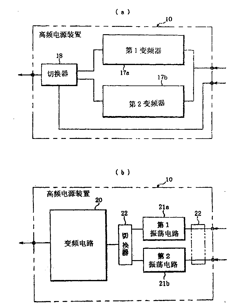
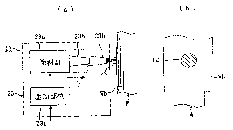
The invention provides a high-frequency induction heating device which can simply and continuously carry out quenching and annealing on a workpiece on a heating device and feasibly carry out quenching and annealing with specified conditions so as to easily and stably obtain a workpiece with favorable quenching and annealing quality. The high-frequency induction heating device comprises a heating coil, a high-frequency power supply, a cooling device, a mark endowing device and a control device. The control device is characterized by providing high-frequency currents for quenching to the heating coil from the high frequency power supply, carrying out quenching on a quenching part of the workpiece, providing high frequency currents for annealing to the heating coil from the high frequency power supply after quenching, carrying out annealing on an annealing part of the workpiece, and then running the mark endowing device after the annealing of the workpiece so as to endow a prescriptive mark to a non-quenching and non-annealing part of the workpiece. The high-frequency power supply is equipped with a first power supply part which can provide the high frequency currents for the quenching to the heating coil and a second power supply part which can provide the high frequency currents for the annealing to the heating coil.

Description

technical field [0001] The present invention relates to a high-frequency induction heating device capable of performing quenching and annealing of various workpieces simply and continuously by high-frequency induction heating with one heating device. Background technique [0002] In general, when quenching or annealing a specified part of the outer peripheral surface of a shaft-shaped workpiece such as a gear shaft, high-frequency induction heating is used in which eddy currents are induced by high-frequency current at a specified frequency to induce heating at the specified position. device. Hitherto, such a high-frequency induction heating device includes a heating coil, a cooling device, a high-frequency power source capable of generating a high-frequency current of a predetermined frequency suitable for quenching or annealing, and the like. [0003] Then, when quenching is performed, a high-frequency current for quenching is supplied from the heating device to the heati...

Claims


Application Information

Patent Timeline
Patent Type & Authority Applications(China)
IPC IPC(8): C21D1/42C21D9/28
CPCY02P10/25
Inventor 宫崎力
Owner 宫电高周波设备(上海)有限公司
Learn More