Rotary lower leather apron tension bracket device of ring spinning machine

A rotary spinning frame technology, applied to spinning machines, textiles, papermaking, drafting equipment, etc., can solve problems such as flower wool and sundries that are not easy to remove, have not been popularized and applied, and affect spinning quality, etc., to achieve improvement The effect of drafting effect, novel technology, good economic benefit and social benefit

Inactive Publication Date: 2010-06-02
秦锡沧
View PDF1 Cites 2 Cited by
  • Summary
  • Abstract
  • Description
  • Claims
  • Application Information

AI Technical Summary

Problems solved by technology

The device uses a rotary sleeve to locate the lower apron. When rotating, the lower apron is controlled by the outer rib of the rotary sleeve in the middle of the rotary sleeve and cannot be moved out. The flower hairs and sundries in the sleeve form a floral dress i

Method used


Image

  • Rotary lower leather apron tension bracket device of ring spinning machine
  • Rotary lower leather apron tension bracket device of ring spinning machine
  • Rotary lower leather apron tension bracket device of ring spinning machine

Examples


Embodiment Construction

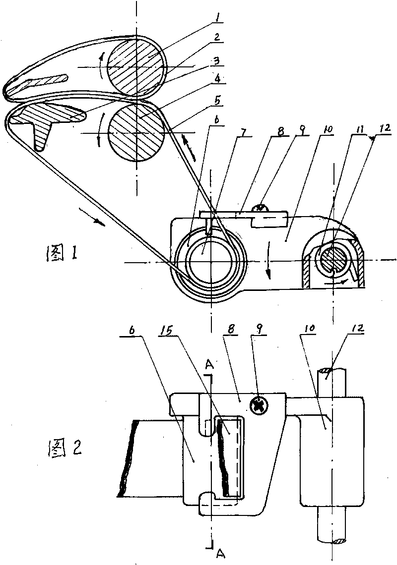
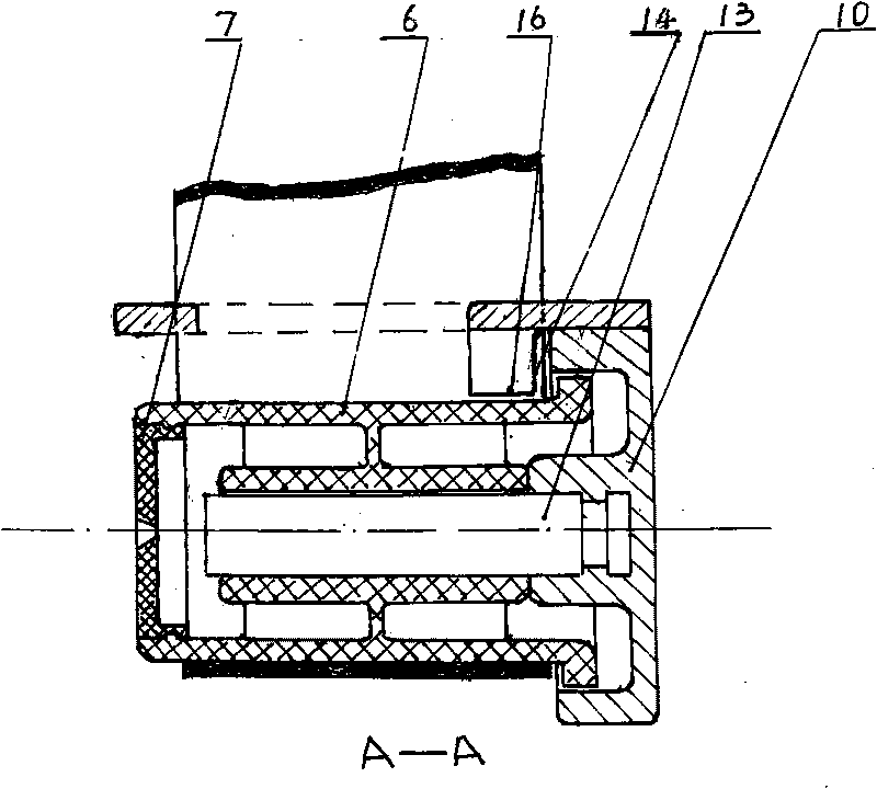
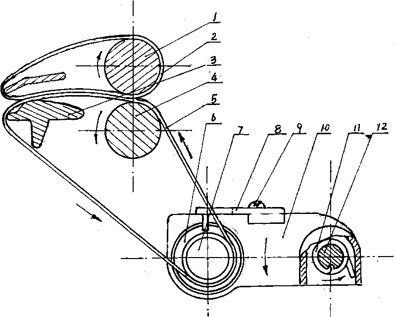
[0015] See figure 1 , figure 2 , image 3 , Is an embodiment of the rotating lower apron tension frame device of the ring spinning frame of the present invention. Including upper apron 2, lower apron 5, top roller 1, roller shaft 4, lower pin 3 and rotating tension structure. The rotating tension structure is composed of a rotating sleeve 6, a cover 7, a tension frame body 10, a steel shaft 13, a limit control frame 8, a tension frame shaft 12, a tension spring 11 and a bolt 9. When working, the tension spring 11 causes the lower apron 5 under tension to drive the rotating sleeve 6 on the steel shaft 13 to rotate. The circular diameter of the lower apron of the rotating sleeve 6 is equal to the outer end, and the rotating sleeve 6 The raised circular table extends into the circular cavity of the tension frame body 10 and maintains a rotation gap with the circular cavity of the tension frame body 10. The outer end surface of the rotating sleeve 6 is sealed with a cover 7.

[00...


PUM


Abstract

The invention provides a rotary lower leather apron tension bracket device of a ring spinning machine, comprising an upper leather apron, a lower leather apron, a leather roller, a roller shaft, a lower pin and a lower leather apron rotating tension mechanism. The lower leather apron drives a rotary sleeve on a steel shaft to rotate under the action of a tension spring on a tension bracket shaft. The invention is characterized in that the diameter of the lower leather apron driving position of the rotary sleeve is equal to the diameter of the outer end of the rotary sleeve, a bulged annular table at the inner end of the rotary sleeve extends into a circular cavity of a tension bracket body and keeps a rotary gap with the circular cavity of the tension bracket body, and the end surface of the outer end of the rotary sleeve is sealed by a cover. A limiting control bracket for controlling the lower leather apron is arranged above the tension bracket body and controls the outer ring of the lower leather apron so that the lower leather apron driven by tension is limited and controlled in the open control groove of the limiting control bracket, the bottom surface of the limiting control bracket is provided with a long-strip stopping block bulging downwards, the annular table at the inner end of the rotary sleeve is limited in the circular cavity of the tension bracket body by the side edge of the long-strip stopping block, and a rotating gap is kept between the bottom edge of the long-strip stopping block and the rotary sleeve. The invention has the advantages of reasonable structure and novel technology, can effectively and reasonably control the lower leather apron to drive the rotary sleeve to rotate in a limiting mode, and is convenient to remove shade yarns, impurities and formed cotton clothes which drop in the rotary sleeve.

Description

Technical field [0001] The invention belongs to a lower apron tension device in a drafting mechanism of a ring spinning frame in the textile industry, in particular to a rotating lower apron tension frame device for a ring spinning frame. Background technique [0002] In the textile industry, the lower apron tension device in the drafting mechanism of the ring spinning frame is one of the key mechanisms of the equipment, which is closely related to energy saving and consumption reduction, the service life of the lower apron, spinning quality and stable production in the workshop. At present, spinning frames at home and abroad still use the tension method in which the tension bar and the lower apron directly rub each other. This method has high friction resistance, high power consumption and energy consumption, and the lower apron has a short service life. The “edge” phenomenon, especially when the temperature and humidity of the workshop are increased or when the workshop is stop...

Claims


Application Information

Patent Timeline
IPC IPC(8): D01H5/86
Inventor 秦浩华秦锡沧
Owner 秦锡沧
Why Eureka
Try Eureka