Moving-iron type linear motor coil array power-driven allocation method

A technology of linear motors and coil arrays, applied to electrical components, electromechanical devices, electric components, etc., can solve the problem of increasing the number of power drives, achieve the effects of reducing the number of power drives, improving work efficiency, and saving costs

Active Publication Date: 2010-06-02
TSINGHUA UNIV
View PDF3 Cites 14 Cited by
  • Summary
  • Abstract
  • Description
  • Claims
  • Application Information

AI Technical Summary

Problems solved by technology

However, for the moving iron type linear motor studied in the present invention, if the stroke length is to be lengthened, the stator coil must

Method used


Image

  • Moving-iron type linear motor coil array power-driven allocation method
  • Moving-iron type linear motor coil array power-driven allocation method
  • Moving-iron type linear motor coil array power-driven allocation method

Examples


Example Embodiment

[0044] Examples:

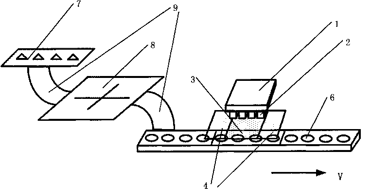
[0045] reference figure 1 4. Demonstrate the transition process of the mover 1 driving the distribution state during the movement, in order to further understand the present invention.

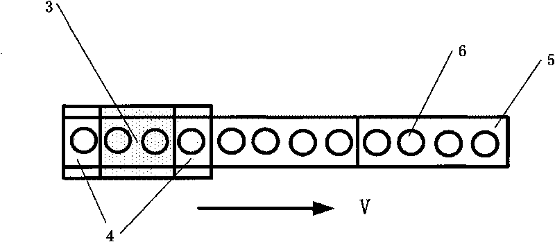
[0046] The maximum speed V of the mover 1 max = 1m / s, the maximum switching time T = 0.1ms for the stator coil array 6 to turn on or off the driver through the switch device 8 = 0.1ms, according to the transition state area 4 width calculation formula L≥V max *T, take L=30mm.

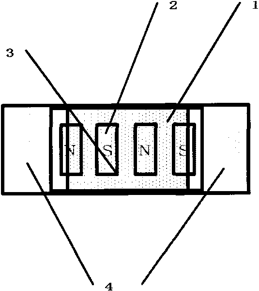
[0047] Under the premise of ensuring that the electromagnetic interaction between the covering coil and the magnetic steel array under the mover magnetic steel array 2 will not produce edge effects, the working state area 3 takes the largest size of the covered coil periphery, that is, the length of the working state area 3 along the direction of movement is 60mm . The inner frame of the transition state area is the same size as the working state area. The inner frame of the transition state area expands t...


PUM


Abstract

The invention relates to a moving-iron type linear motor coil array power-driven allocation method, which comprises the steps of; dividing a rectangular stator coil array of a moving-iron type linear motor into n partition areas, wherein each partition area is divided into an operating condition area and a transition condition area; determining and the total number of power drivers according to the number of coils in each partition area to form a driver array; and connecting the driver array with the stator coil array through a switchgear, and ensuring that each driver is connected with the coil at the corresponding position in each partition area through the switchgear. The method determines the coverage area of the coil array according to a position at which a rotor magnetic steel array is positioned, and controls the on/off and the current of the coils by utilizing the limitation of the transition condition area so as to realize the large stroke linear motion of the rotor. The method can solve the problems of complex structure and expensive total cost of driver equipment which are caused by excessive drivers caused by multiple number of the stator coils.

Description

Technical field [0001] The invention relates to a method for connecting a moving iron linear motor coil array and a driver, in particular to a driver distribution method. Background technique [0002] Linear motor is a motor that converts electrical energy into linear motion mechanical energy without any intermediate conversion devices. It changes the traditional intermediate conversion system such as chains, wire ropes, conveyor belts, rack screws, etc., overcomes the shortcomings of traditional mechanical conversion mechanisms such as transmission chain length, large volume, low efficiency, and poor precision. It has large starting thrust and transmission rigidity. High, fast dynamic response, high positioning accuracy, unlimited stroke length, etc. Its application range is very wide, such as machine tool work, train driving, material transportation, automatic plotter, household appliances, semiconductors, etc. In terms of linear motor structure, it can be divided into many f...

Claims


Application Information

Patent Timeline
IPC IPC(8): H02K41/02
CPCH02K41/02
Inventor 朱煜胡金春廖凯汪劲松尹文生杨开明张鸣徐登峰段广洪张利
Owner TSINGHUA UNIV
Why Eureka
Try Eureka