High-precision positioning method applied to rotary cutter

A positioning method and disc shearing technology, which are applied to shearing equipment, shearing devices, metal processing equipment, etc., can solve the problems of inability to guarantee the precision required by the process, inherent errors of disc shearing machinery, mechanical clearance, mechanical wear, etc., and achieve Improve the success rate of edge trimming, overcome the mechanical gap error, and stabilize the control effect

Inactive Publication Date: 2010-06-09
武钢集团有限公司
View PDF0 Cites 11 Cited by
  • Summary
  • Abstract
  • Description
  • Claims
  • Application Information

AI Technical Summary

Problems solved by technology

[0006] At present, the widely used disc shear control systems have adopted advanced programmable logic controllers (PLC) to realize the positioning of the gap and overlap, but due to the extremely high positioning control accuracy requirements of the disc shears (such as some types of Oriented silicon steel edge trimming requires clearance positioning accuracy within ±0.02mm), and after a period of use, the mechanical transmission part of the disc shears inevitably has mechanical inherent errors, mechanical clearances, mechanical wear, etc., and mechanical reasons early The resulting error will increase cumulatively with the prolongation of the use time. The traditional dynamic reverse gap compensation method cannot guarantee the accuracy required by the process. Often, manual adjustment is required after positioning, so it can only be defined as semi-automatic adjustment and positioning.

Method used


Image

  • High-precision positioning method applied to rotary cutter
  • High-precision positioning method applied to rotary cutter
  • High-precision positioning method applied to rotary cutter

Examples


Embodiment Construction

[0021] The present invention will be further described in detail below with reference to the accompanying drawings and specific embodiments.

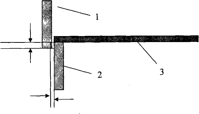
[0022] The schematic diagram of the working principle of the disc shear is as follows image 3 shown. As shown in the figure, the cutter head of the disc scissors is composed of two vertical circular blades that are dislocated up and down, that is, the disc cutter upper blade 1 and the disc cutter blade 2. The running strip 3 passing between the two blades is cut by adjusting a certain gap and overlap between the upper disc cutter 1 and the disc cutter blade 2 . When the running strip 3 passes between the two blades, due to the disc shearing blade 1 and the disc cutting blade 2 applying a certain shearing force to the running strip 3, the contact area between the running strip 3 and the blade is deformed, With the increase of the bite depth, the deformation of the running strip 3 also increases, and when the deformation reaches a cert...


PUM


Abstract

The embodiment of the invention discloses a high-precision positioning method applied to a rotary cutter. For the adjustment of the lap of a cutter head, a mechanical structure and an electric structure of the rotary cutter are combined together to simplify the calculation process and change the control mode of a servo motor into a speed mode control. The high-precision positioning method overcomes mechanical clearance errors of the superposition of a plurality of gears; and the horizontal clearance is controlled by an improved mechanical clearance compensation method to eliminate the influence on the positioning precision of the cutter head because of the mechanical clearance changes caused by abrasion. The high-precision positioning method has the advantages of high positioning precision, simple program implementation algorithm, stable control effect and quick response speed, can improve the trimming material yield of strip steel and reduce the time for variable specification adjustment, and is very helpful for improving the output of acid cleaning strip steel and increasing the economic benefit of a production line.

Description

technical field [0001] The invention relates to the technical field of disc shear control, in particular to a high-precision positioning method applied to a disc shear. Background technique [0002] Pickling is an important process in the production of modern strip steel. In the process of pickling production, after the strip has been hot-rolled, there are often edge defects such as cracked edges and uneven edges. At this time, it is necessary to adopt a certain shearing process to cut the edge of the strip according to the process requirements to eliminate the edge defects of the hot-rolled strip, obtain high-quality products, and provide high-quality raw materials for the subsequent process (cold rolling). . [0003] It can be known from the working principle of the disc shear that the gap and overlap of the disc shear directly determine the quality of the strip trimming. It is easy to cause burrs on the edge of the strip, the shearing mouth is not smooth, and even the s...

Claims


Application Information

Patent Timeline
Patent Type & Authority Applications(China)
IPC IPC(8): B23D19/00
Inventor 梅勇
Owner 武钢集团有限公司
Why Eureka
Try Eureka