High-tolerance flexibility capture mechanism for space environment

A space environment, large-tolerance technology, applied in the direction of manipulators, program-controlled manipulators, space navigation equipment, etc., can solve the problems of small capture tolerances and inability to meet the accuracy requirements of capture manipulators, and achieve large capture tolerances and small quality , capture the effect of small impact

Inactive Publication Date: 2010-06-09
HARBIN INST OF TECH
View PDF0 Cites 31 Cited by
  • Summary
  • Abstract
  • Description
  • Claims
  • Application Information

AI Technical Summary

Problems solved by technology

[0003] The purpose of the present invention is to solve the problem that the existing capture mechanism has a small capture tolerance and cannot

Method used


Image

  • High-tolerance flexibility capture mechanism for space environment
  • High-tolerance flexibility capture mechanism for space environment
  • High-tolerance flexibility capture mechanism for space environment

Examples


specific Embodiment approach 1

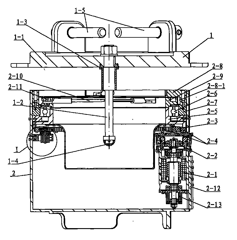
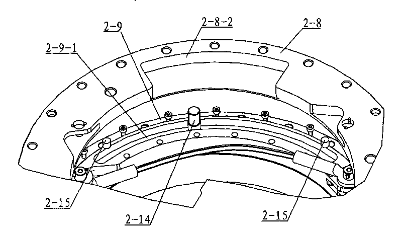
[0007] Specific implementation mode one: combine figure 1 and figure 2 Describe this embodiment. This embodiment includes a capture interface device 1 and a capture device 2. The capture device 2 includes a DC brushless motor 2-1, a harmonic reducer 2-2, a pinion 2-3, an internal gear 2-4, Moment sensor 2-5, thin-wall bearing 2-6, connecting ring 2-7, fixed ring 2-8, rotating ring 2-9, three steel wire ropes 2-10, rotating shaft 2-11 and capturing support cylinder 2-12, harmonious The input end of the wave reducer 2-2 is connected to the output end of the DC brushless motor 2-1, and the DC brushless motor 2-1 and the harmonic reducer 2-2 are arranged at the lower part of the inner cavity of the capture support cylinder 2-12, And the DC brushless motor 2-1 is fixedly mounted on the inner wall of the capture support cylinder 2-12 through the connector, and the rigid wheel on the harmonic reducer 2-2 is fixedly connected with the side wall of the capture support cylinder 2-12 t...

specific Embodiment approach 2

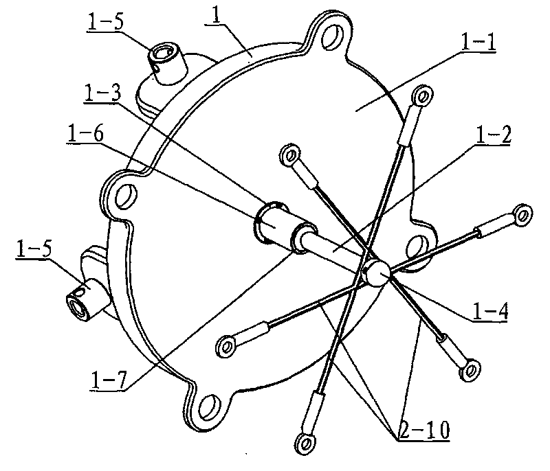
[0008] Specific implementation mode two: combination figure 1 and figure 2 To illustrate this embodiment, the capture interface device 1 of this embodiment includes a capture interface plate 1-1, a capture cone 1-2, a capture flange 1-3, a capture guide light 1-4 and at least three connecting pins 1-5, The upper end of the capture cone 1-2 is connected to the capture flange 1-3, and the assembly of the capture flange 1-3 and the capture cone 1-2 is vertically arranged at the lower end of the capture interface plate 1-1, and the capture flange 1-3 passes through The connector is fixedly connected to the lower end surface of the capture interface board 1-1, the capture guide light 1-4 is installed on the lower end of the capture cone 1-2, and at least three connecting pins 1-5 are evenly arranged on the bottom of the capture interface board 1-1. on the upper end face. Capture guide lights 1-4 play the role of capture guide. The capture interface device 1 is connected to the ...

specific Embodiment approach 3

[0009] Specific implementation mode three: combination figure 2 Describe this embodiment. The difference between this embodiment and the second embodiment is that the capture interface device 1 is further provided with a connecting shaft 1-6, and the connecting shaft 1-6 is arranged between the capturing flange 1-3 and the capturing cone 1-2. , and one end of the connecting shaft 1-6 is sleeved on the catching cone 1-2, and the other end of the connecting shaft 1-6 is connected with the catching flange 1-3. The purpose of this design is to form a step 1-7 between the catching cone 1-2 and the connecting shaft 1-6, and the step 1-7 can effectively prevent the wire rope from falling off. Other components and connections are the same as those in the second embodiment.


PUM


Abstract

The invention provides a high-tolerance flexibility capture mechanism for space environment and relates to a capture mechanism; the capture mechanism solves the problems that the existing capture mechanism has low capture tolerance and can not meet high precision requirements of a capture mechanical arm; in the invention, the input end of a harmonic wave reducer is connected with the output end of a direct current brushless motor, the direct current brushless motor is fixedly arranged on an inner wall of a capture supporting barrel, a small gear is arranged on the output end of the harmonic wave reducer, the small gear is meshed with an inner gear, the inner gear is fixedly connected with a force moment sensor which is fixedly connected with a rotation ring, a fixing ring is fixedly connected with the inner side wall of the capture supporting barrel by a connecting ring, three steel wire nets are distributed in the inner cavity of the fixing cavity and the rotating ring, one end of each steel wire is fixedly connected with the inner wall of the fixing ring, the other end of each steel wire is connected with the rotating ring by a rotating shaft, and a capture cone on a capture interface device is connected with the three steel wires; the high-tolerance flexibility capture mechanism is used for capturing space load cabin under spatial high tolerance and microgravity environment.

Description

technical field [0001] The present invention relates to a capture mechanism. Background technique [0002] Most of the current space capture mechanisms adopt the rigid capture principle, which has a large capture impact, which has a great impact on the capture carrier and the capture load, and may cause damage to the system in severe cases. However, the existing capture mechanism has a small capture tolerance and cannot meet the high precision requirements of the capture robot arm. Contents of the invention [0003] The purpose of the present invention is to solve the problem that the existing capture mechanism has a small capture tolerance and cannot meet the high precision requirements of the capture manipulator, and provides a large-tolerance flexible capture mechanism for space environments. [0004] The invention includes a capture interface device and a capture device, the capture device includes a DC brushless motor, a harmonic reducer, a pinion, an internal gear, ...

Claims


Application Information

Patent Timeline
IPC IPC(8): B25J9/08B64G4/00
Inventor 谭益松刘宏刘伊威倪风雷
Owner HARBIN INST OF TECH
Why Eureka
Try Eureka