Biomass molding fuel equipment

A technology for forming fuel and biomass, which is applied in material forming presses, presses, manufacturing tools, etc., can solve the problems of increased investment, short working life, fast wear of key components, etc., to reduce equipment energy consumption and equipment. The effect of cost, improved life of wearing parts, and strong continuous operation capability

Active Publication Date: 2012-04-04
GUANGZHOU INST OF ENERGY CONVERSION - CHINESE ACAD OF SCI
View PDF0 Cites 0 Cited by
  • Summary
  • Abstract
  • Description
  • Claims
  • Application Information

AI Technical Summary

Problems solved by technology

[0005] (1) The wearing parts of biomass briquette fuel equipment have short service life and poor equipment stability
Most of the biomass molding equipment is improved from the feed production equipment. The biomass raw material wears out the key components quickly, the working life is short, and the operation of the equipment is unstable, which affects the large-scale production;
[0006] (2) Biomass briquette fuel equipment has poor raw material adaptability and low continuous operation capacity
The supply of raw materials is affected by seasonal costs, transportation radius, etc., and the variety changes greatly. Since the equipment cannot adapt to the diversity of raw materials, the equipment has to work intermittently. Half of the time in a year is idle, resulting in waste of resources and serious equipment loss. , increasing the equipment recovery period
To meet the continuous production of equipment, it is necessary to increase the reserve warehouse. This method will lead to an increase in investment. The best way is that the equipment has a wide range of raw material adaptability, so that the additional investment can be minimized

Method used


Image

  • Biomass molding fuel equipment
  • Biomass molding fuel equipment
  • Biomass molding fuel equipment

Examples


Embodiment Construction

[0020] The content of the present invention will be described in further detail below in conjunction with the accompanying drawings and specific embodiments.

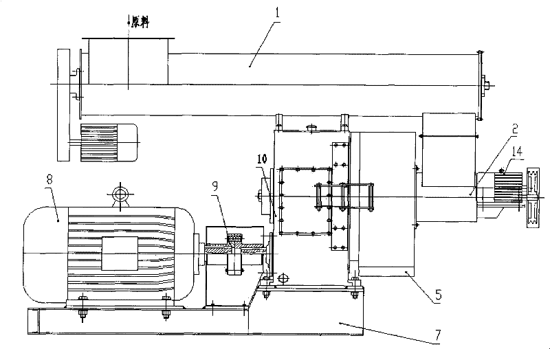
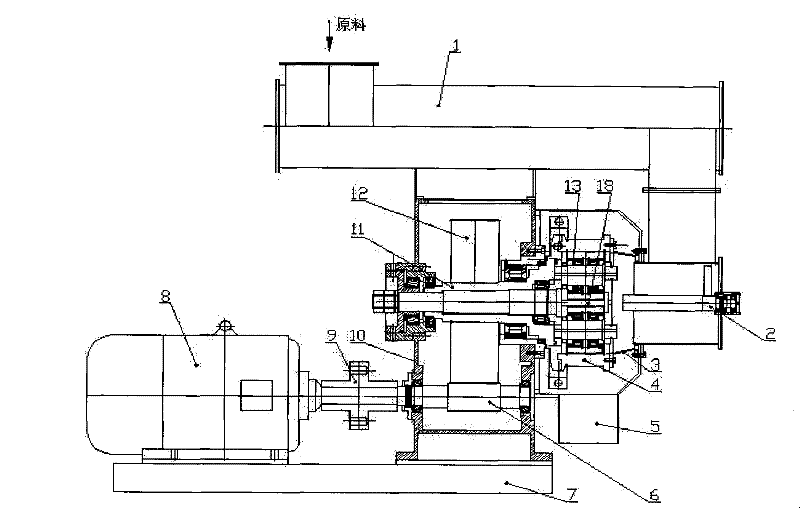
[0021] see figure 2 As shown, a biomass briquette fuel equipment includes a base 7, a coupling 9, a frequency conversion feeder 1, a main motor 8 fixed on the base 7, and a reduction box 10. On the other side of the reduction box 10, there is Forced feeder 2, one end of the coupling 9 is connected to the main motor 8, and the other end is connected to the reduction box 10, the frequency conversion feeder 1 is connected to the forced feeder 2 through the flange, and the reduction box 10 is connected to the forced feeder 2 is also provided with a ring die 4, and the ring die 4 is provided with pressure rollers. The reduction box 10 includes a drive shaft 6, a reduction gear 12, and a hollow shaft 11. The hollow shaft 11 is provided with a main shaft 18, and the drive shaft 6 Connected with the coupling 9, the reduction ...


PUM


Abstract

The invention discloses biomass molding fuel equipment. The equipment comprises a base, a coupling, a variable-frequency feeder, a main motor and a reduction gearbox which are fixed on the base, wherein one end of the coupling is connected with the main motor, and the other end of the coupling is connected with the reduction gearbox; a compulsory feeder is arranged on the other side of the reduction gearbox; the variable-frequency feeder and the compulsory feeder are connected; a ring die is arranged between the reduction gearbox and the compulsory feeder, in which a compression roller is arranged; a driving shaft, a reduction gear, a hollow shaft and a main shaft are arranged in the reduction gearbox; the driving shaft is connected with the coupling; the reduction gearbox is arranged at the periphery of the hollow shaft and is engaged with the hollow shaft; one end of the reduction gearbox is connected with the driving shaft; the equipment also comprises a feeding tray, of which one end is arranged in the ring die, and the other end is connected with the compulsory feeder; the hollow shaft is connected to the compulsory feeder by passing through the reduction gearbox; and the ring die is coupled at one end of the hollow shaft. The equipment is not only suitable for wood raw materials, but also suitable for straw raw materials.

Description

technical field [0001] The invention relates to the technical field of biomass briquette fuel equipment. Background technique [0002] Due to the massive development and utilization of non-renewable fossil fuels, serious energy crisis and environmental crisis have been brought about, which have brought serious problems to the sustainable development of social economy and the living environment of human beings. Today, the development and utilization of renewable energy has become the focus of research and development in various countries. Biomass resources are the only resources that can be stored and transported in renewable energy, and have become a hot spot in research and development in renewable energy. Biomass briquette fuel is easy to realize large-scale production and use, and the convenience of using biomass briquette fuel particles is comparable to that of gas, oil and other energy sources. Therefore, the development of biomass briquette fuel pellet equipment has g...

Claims


Application Information

Patent Timeline
Patent Type & Authority Patents(China)
IPC IPC(8): B30B11/20B30B15/00B30B15/30
CPCB30B11/208B30B11/207B30B11/201
Inventor 姜洋潘贤齐刘贵锋李伟振
Owner GUANGZHOU INST OF ENERGY CONVERSION - CHINESE ACAD OF SCI
Why Eureka
Try Eureka