
Device to determine the angle of rotation, especially for the steering shaft of a vehicle

A technology for determining devices and motor vehicles, which is applied in the use of electrical devices and electromagnetic/magnetic devices to transmit the direction of sensing components, steering mechanisms, etc., which can solve the problems of mutual influence between systems and cannot avoid mutual influence, and achieve the effect of accurate measurement.

Active Publication Date: 2010-06-09
海拉有限双合股份公司
View PDF7 Cites 25 Cited by
  • Summary
  • Abstract
  • Description
  • Claims
  • Application Information

AI Technical Summary

Problems solved by technology

The combination of two systems of inductive measurement in the form of magnetic sensors is likewise only conditionally possible, since the two systems can also influence each other or cannot avoid mutual influence

Method used


Image

  • Device to determine the angle of rotation, especially for the steering shaft of a vehicle
  • Device to determine the angle of rotation, especially for the steering shaft of a vehicle
  • Device to determine the angle of rotation, especially for the steering shaft of a vehicle

Examples


Embodiment Construction

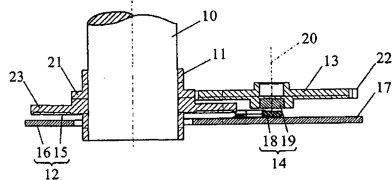
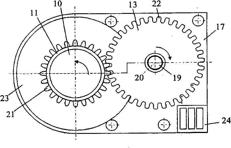
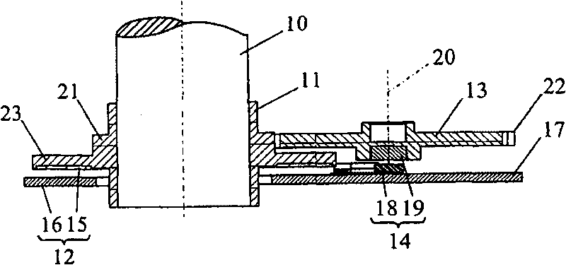
[0020] figure 1 An exemplary embodiment of a rotational angle determination device 1 according to the invention is shown. The device 1 is used to determine the angular position of a rotationally movable shaft 10 which may be a component of a steering system of a motor vehicle and which is rotationally connected to a steering shaft. Mounted on said rotating shaft 10 is a main rotor 11 which rotates together with the rotating shaft 10 . The main rotor 11 has a flange region 23 , wherein an induction rotor 15 is mounted on the end plane of the flange region. The flange area 23 extends with the induction rotor 15 parallel to and spaced apart from a carrier 17 on which a stator 16 is mounted. The induction rotor 15 and the stator 16 form a first sensor unit 12 which is designed as an inductively acting sensor. The principle of an inductively acting sensor is based on the fact that inductively coupled-out energy flows into an induction rotor 15 which in turn interacts inductively...


PUM


Abstract

The present invention relates to a rotation angle determination device (1) used for determining the rotation angle position of a rotating shaft (10). The device comprises the following components: a main rotor (11) which is coupled with the rotating shaft (10) and is provided with a first sensor unit (12) for determining the rotation angle position of the main rotor (11); and an additional rotor (13) which is rotatably coupled with the main rotor (11) and is provided with a second sensor unit (14) for determining the rotation angle position of the additional rotor (13). According to the invention, each of the sensor unit (12, 14) is provided with at least one sensor with induction effect and at least one sensor with magnetic effect.

Description

technical field [0001] The invention relates to a rotational angle determination device for determining the rotational angular position of an axis of rotational movement. The device has a main rotor coupled to the shaft of rotational movement, on which a first sensor unit is arranged for determining the rotational angular position of the main rotor. Furthermore, the device has an additional rotor rotationally coupled to the main rotor, on which a second sensor unit is arranged for determining the rotational angular position of the additional rotor. Background technique [0002] A rotational angle determination device of the described type is known from EP 0 389 669 A1. The device described in this document serves to determine the angular position of a rotationally moving shaft, which is designed as a steering shaft in a motor vehicle. The first sensor unit and the second sensor unit are each formed as a potentiometer. The first potentiometer is directly coupled to the sha...

Claims


Application Information

Patent Timeline
Patent Type & Authority Applications(China)
IPC IPC(8): B62D15/02G01B7/30G01D5/12
CPCB62D15/0215G01D5/145G01D5/20G01D2205/26
Inventor N·拉班H·韦塞林克M·绍尔H·伊尔勒M·托法尔
Owner 海拉有限双合股份公司
Learn More