Supercharge Your Innovation With Domain-Expert AI Agents!

Fluid pump with an integrated mounting interface

A fluid pump, installation structure technology, applied in the parts, pump components, transportation and packaging of the pumping device for elastic fluid, can solve the problem of improper installation of fluid pump, heavy equipment and tools, etc.

Inactive Publication Date: 2010-06-09
GM GLOBAL TECH OPERATIONS LLC
View PDF0 Cites 0 Cited by
  • Summary
  • Abstract
  • Description
  • Claims
  • Application Information

AI Technical Summary

Problems solved by technology

These additional parts, equipment and tools are very heavy and the fluid pump is prone to being installed incorrectly

Method used


Image

  • Fluid pump with an integrated mounting interface
  • Fluid pump with an integrated mounting interface
  • Fluid pump with an integrated mounting interface

Examples


Embodiment Construction

[0021] The following detailed description and drawings describe and illustrate various exemplary embodiments of the invention. This description and drawings serve to enable those skilled in the art to make and use the invention and are not intended to limit the scope of the invention in any way.

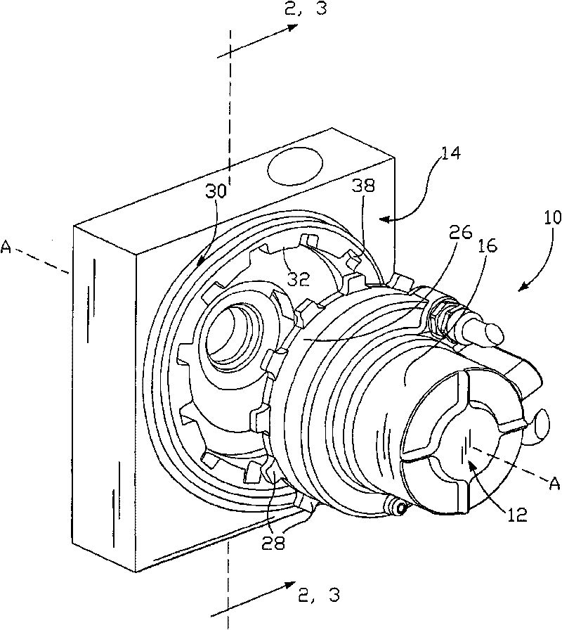
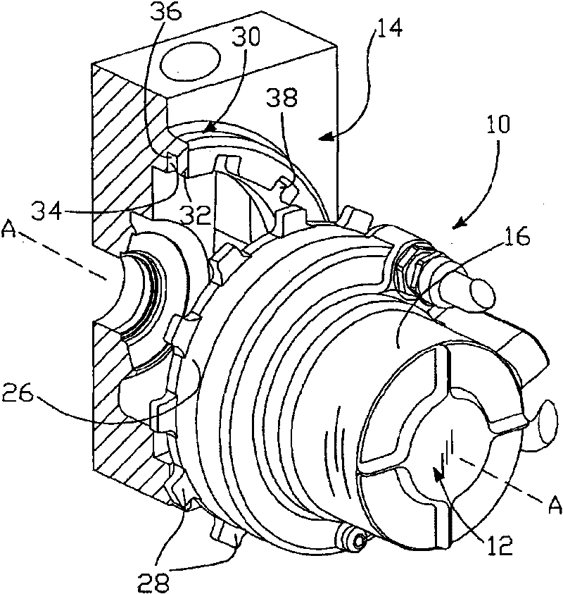
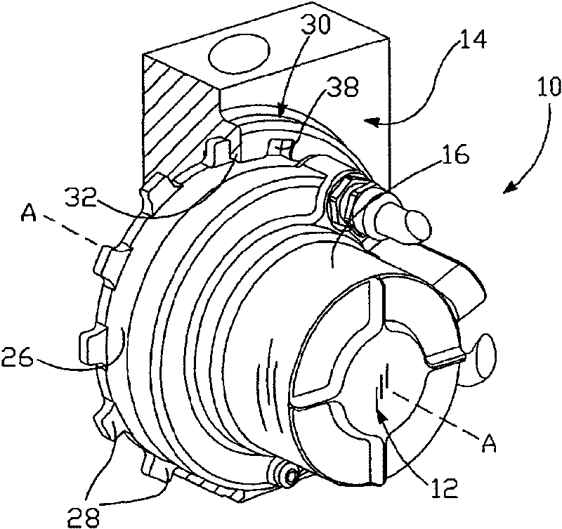
[0022] figure 1 A fluid pump assembly 10 is shown in accordance with an embodiment of the invention. The fluid pump assembly 10 includes a fluid pump 12 and a corresponding mounting structure 14 . It should be understood that the fluid pump 12 may be any type of fluid pump as required, such as a flexible impeller pump, a piston pump, a rotary vane pump, and the like. The fluid pump 12 is adapted to cooperate with the mounting structure 14 and to rotate about the axis A from a first position to a second position. The second position is also known as the locked position, as image 3 As shown, a twist-lock connection is formed. It should be understood that the fluid pump 12 can be ...


PUM


Abstract

A fluid pump assembly for a fuel cell system is disclosed, the fluid pump assembly including a mounting structure having a receiving element formed thereon and a fluid pump having at least one locking element formed thereon, wherein the mounting structure is a lower end unit of the fuel cell system, and wherein the receiving element captures the locking elements of the fluid pump to militate against lateral, axial, and rotational movement of the fluid pump.

Description

technical field [0001] The present invention relates to a fluid pump assembly, and more particularly to a fuel cell system including the fluid pump assembly. Background technique [0002] Fuel cells have been proposed for various applications as a clean, efficient and environmentally responsible energy source. Individual fuel cells can be stacked together in succession to form a fuel cell stack. The fuel cell stack is capable of supplying enough electricity to power an electric vehicle. In particular, fuel cell stacks have been identified as ideal replacements for conventional internal combustion engines used in modern vehicles. [0003] One type of fuel cell stack is known as a proton exchange membrane (PEM) fuel cell stack. A typical PEM fuel cell consists of three basic components: cathode, anode, and electrolyte membrane. The cathode and anode typically include finely divided catalysts, such as platinum, supported on carbon particles and mixed with ionomers. An elec...

Claims


Application Information

Patent Timeline
Patent Type & Authority Applications(China)
IPC IPC(8): F01P5/10H01M8/02H01M8/04
CPCF04C2230/60F04B53/22F04C2240/30Y02E60/50H01M8/04029F01C21/10H01M8/04059Y10T137/7069
Inventor B·安德里斯-肖特T·P·米格利奥尔J·D·赖恩维尔
Owner GM GLOBAL TECH OPERATIONS LLC
Features
  • R&D
  • Intellectual Property
  • Life Sciences
  • Materials
  • Tech Scout
  • Unparalleled Data Quality
  • Higher Quality Content
  • 60% Fewer Hallucinations
Learn More