Balance valve

A technology of balancing valve and valve body, applied in the field of balancing valve, can solve problems such as affecting the safety performance of cranes, poor crane fretting, controlling pressure fluctuations, etc., and achieve the effects of avoiding hidden dangers of operation safety, smooth movement and eliminating jitter.

Inactive Publication Date: 2010-06-09
XUZHOU HEAVY MASCH CO LTD
View PDF0 Cites 10 Cited by
  • Summary
  • Abstract
  • Description
  • Claims
  • Application Information

AI Technical Summary

Problems solved by technology

[0005] However, since the control pressure will fluctuate with the change of system pressure, in practical applications, the opening of the smooth valve will fluctuate with the pulsation of system pressure, and low-frequency vibration phenomenon, commonly known as jitter
In particular, the crane showed poor micro-movement and unreliable work under the condition of small opening of the valve port
Therefore, in the above-mentioned several special working conditions, there are hidden dangers affecting the safety performance of the crane
[0006]In view of this, it is urgent to develop a balance valve that can adapt to the hydraulic control system of the crane, so that there will be no jittering phenomenon during fast reversing or load lowering operation , and good fretting, to effectively avoid safety hazards caused by controlling oil at high pressure

Method used


Image

  • Balance valve
  • Balance valve
  • Balance valve

Examples


Embodiment Construction

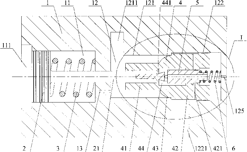
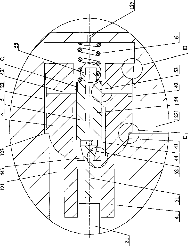
[0031] The core design of the present invention is to improve the structure and positional relationship between the main valve core and the control valve core. The damping structure is designed to improve the movement stability of the main spool.

[0032] The present embodiment will be described in detail below in conjunction with the accompanying drawings.

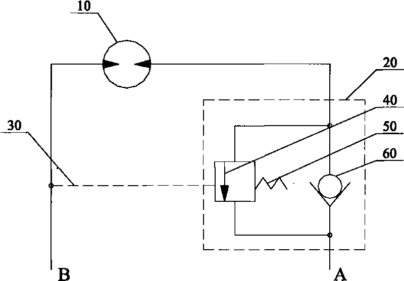
[0033] see figure 2 , which is a schematic structural view of the balance valve provided by the present invention when it is in a non-conducting state.

[0034] Such as figure 2 As shown, the balance valve of the present invention is mainly composed of valve body 1, control piston 2, first spring 3, main spool 4, control spool 5, second spring 6 and other main components. In this paper, the structure and positional relationship of the above-mentioned main components will be described in detail. The realization of the cooperation relationship between the components with sealing requirements can be realized by those skil...


PUM


Abstract

The invention discloses a balance valve. In the balance valve, a main valve core and a control piston are placed in two cavities of a valve body respectively; a control valve core is arranged in a cavity of the main valve core in an embedded mode; when working pressure oil liquid enters the valve body from a second oil opening, the control piston moves to the right to pull the control valve core to move to the right, a second segment of the control valve core is separated from a ring-shaped protrusion of the cavity of the main valve core; the working pressure oil liquid acts on the protruding surface of the outer edge of the main valve core, the main valve core moves to the right, namely the transitional surface of the main valve core is separated from the transitional surface of a second cavity, and the working pressure oil liquid passes the second cavity of the valve body and flows out of the valve body by a first oil opening; because the control valve core needs to be opened before the main valve core is opened and in fine adjustment, the main valve core is still at a closing state and relatively smoothly moves, so that the vibration caused by loading operation is eliminated; and when the control pressure continuously increases, the main valve core moves to the right under an action of the working pressure of the second oil opening, the opening is free from the influence of control pressure, a heavy article can smoothly fall at a controlled speed, and the control accuracy is improved.

Description

technical field [0001] The invention relates to a hydraulic control element, in particular to a balance valve. Background technique [0002] With the rapid development of the national economy and infrastructure, cranes have been widely used in various engineering constructions. Limited by their operating characteristics, the safety requirements of cranes have always been in a prominent position. [0003] When the hydraulic system is working, if the load of the actuator is a load, and the direction of the load is consistent with the direction of motion, a balance valve is required to generate oil flow resistance on the oil return circuit to prevent the hydraulic cylinder or hydraulic motor from being under load. Movement under the action is out of control. For example, in the load lowering condition, the load of the hydraulic motor is hoisting weight. In order to prevent the hydraulic motor from turning faster and faster under the action of hoisting weight, it is necessary t...

Claims


Application Information

Patent Timeline
Patent Type & Authority Applications(China)
IPC IPC(8): F16K17/20F16K31/126F15B13/02
Inventor 刘邦才徐尚国周飞
Owner XUZHOU HEAVY MASCH CO LTD
Why Eureka
Try Eureka