Air conditioner
A technology for air conditioners and container expansion, which is applied in the direction of compressors with reversible cycles, lighting and heating equipment, damage protection, etc., can solve the problems of reduced human comfort, reduced indoor temperature, and reduced indoor temperature
- Summary
- Abstract
- Description
- Claims
- Application Information
AI Technical Summary
Problems solved by technology
Method used
Image

Examples
Embodiment 1
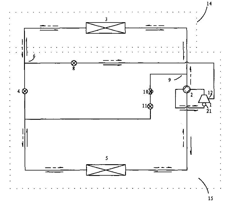
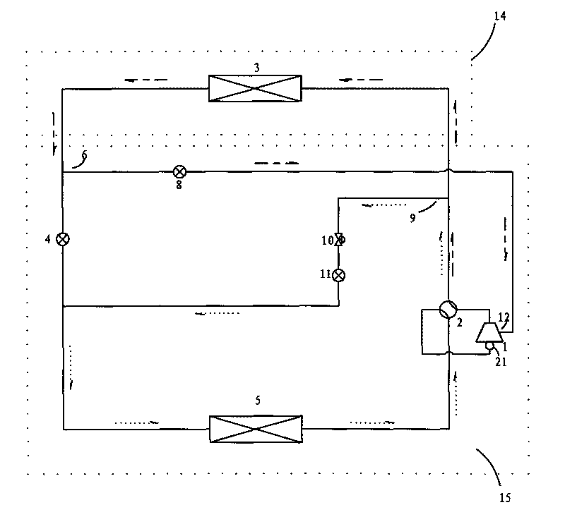
[0028] figure 1 with figure 2 It is a schematic flow diagram of the refrigeration / heating cycle and a schematic flow diagram of the heating-defrosting cycle in Embodiment 1 of the present invention. figure 1 Among them, the indoor unit 14 includes an indoor heat exchanger 3, and the outdoor unit 15 includes a compressor 1, a four-way valve 2, a first throttling mechanism 4, an outdoor heat exchanger 5, an injection enthalpy increasing bypass circuit 6, and an injection Enthalpy-increasing throttling mechanism 8, defrosting bypass circuit 9, defrosting automatic control valve 10, compressor intermediate suction port 12, compressor gas-liquid separator 21 in return air pipe. Here, the first throttling mechanism 4 is an electronic expansion valve, the injection enthalpy increasing throttling mechanism 8 adopts an electronic expansion valve, and the defrosting automatic control valve 10 selects a control valve with an on-off function and a certain throttling capacity.
[0029] ...
Embodiment 2
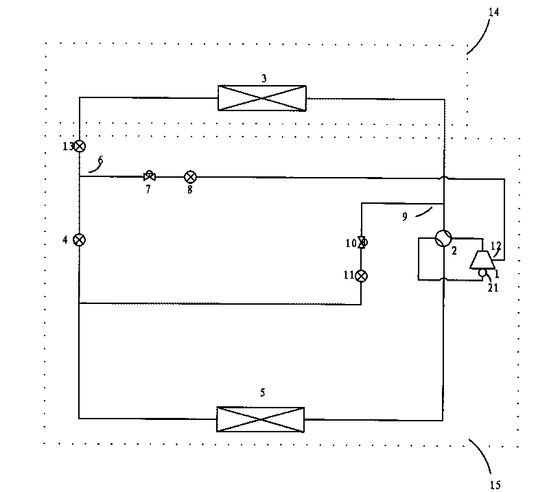
[0033] as attached image 3 As shown, the difference between this embodiment and Embodiment 1 is that a second throttling mechanism 13 is added between the injection enthalpy increase bypass circuit 6 and the indoor heat exchanger 3 , and on the injection enthalpy increase bypass circuit 6 , the injection enthalpy increase automatic control valve 7 is added, and the injection enthalpy increase throttling mechanism 8 uses a capillary tube to control the flow rate of the working fluid passing through the injection enthalpy increase bypass circuit 6 . Through the second throttling mechanism 13 , the first throttling mechanism 4 and the injection enthalpy increasing throttling mechanism 8 to control the flow rate and pressure drop of the respective circuits. A throttling mechanism 11 for defrosting is added behind the original automatic defrosting control valve 10. The automatic defrosting control valve 10 adopts an electric two-way valve, and the throttling mechanism 11 for defro...
Embodiment 3
[0035] as attached Figure 4 As shown, the difference between this embodiment and Embodiment 2 is that: a liquid separation expansion vessel 16 is added between the injection enthalpy increase bypass circuit 6, the first throttling mechanism 4 and the second throttling mechanism 13, wherein the injection increase The enthalpy bypass circuit 6 is connected to the upper part of the liquid separation expansion vessel 16, the first throttling mechanism 4 is connected to the lower part of the liquid separation expansion vessel 16, and the second throttling mechanism 13 is connected to the middle part of the liquid separation expansion vessel 16. The liquid separation expander 16 is equivalent to the effect of a heat exchanger, which can fully vaporize the internal decompression working medium, so that the working medium flowing from the injection enthalpy increasing bypass circuit 6 to the intermediate suction port 12 of the compressor is a gaseous working medium. Mainly, increase ...
PUM
 Abstract
Description
Claims
Application Information
 - R&D
- Intellectual Property
- Life Sciences
- Materials
- Tech Scout
- Unparalleled Data Quality
- Higher Quality Content
- 60% Fewer Hallucinations
Browse by: Latest US Patents, China's latest patents, Technical Efficacy Thesaurus, Application Domain, Technology Topic, Popular Technical Reports.
© 2025 PatSnap. All rights reserved.Legal|Privacy policy|Modern Slavery Act Transparency Statement|Sitemap|About US| Contact US: help@patsnap.com