Device and method for detecting distribution image of each substance in fluid

A technology for fluids and substances, which is applied in the field of devices for detecting the distribution images of various substances in fluids, can solve the problems of small number of projections in a tomographic imaging system, low reconstruction accuracy, and undesired complexity, so as to speed up scanning and processing. , the effect of high detection accuracy and wide application value

Inactive Publication Date: 2010-06-09
ZHEJIANG UNIV
View PDF1 Cites 2 Cited by
  • Summary
  • Abstract
  • Description
  • Claims
  • Application Information

AI Technical Summary

Problems solved by technology

[0005] In the patent CN1372165A, the inventor has proposed a new method of pixel allocation and planar optical path design for optical fiber process tomography with a circular structure, which aims at the shortcomings of square pixels and scanning methods in the original method That is, square pixels are not suitable for circular cross-sections, which will bring theoretical errors. In various scanning methods, such as orthogonal, straight line, three-line, fan-shaped and other scanning structures, they are also similar to circular The structure does not match, and the new structure is circularly symmetrical in terms of pixel allocation and light path layout
[0006] However, the above-mentioned patents also have shortcomings. Due to the method of associating the number of sensing units with the number of pixels, the number of pixels is small, otherwise a large number of sensor units are required, which is a huge problem in terms of system complexity and cost. Not advisable, because the system does not have a scanning device, the number of projections in the tomography system is small, and the reconstruction accuracy is not high, which greatly limits the specific application of this structure

Method used


Image

  • Device and method for detecting distribution image of each substance in fluid
  • Device and method for detecting distribution image of each substance in fluid
  • Device and method for detecting distribution image of each substance in fluid

Examples


Embodiment Construction

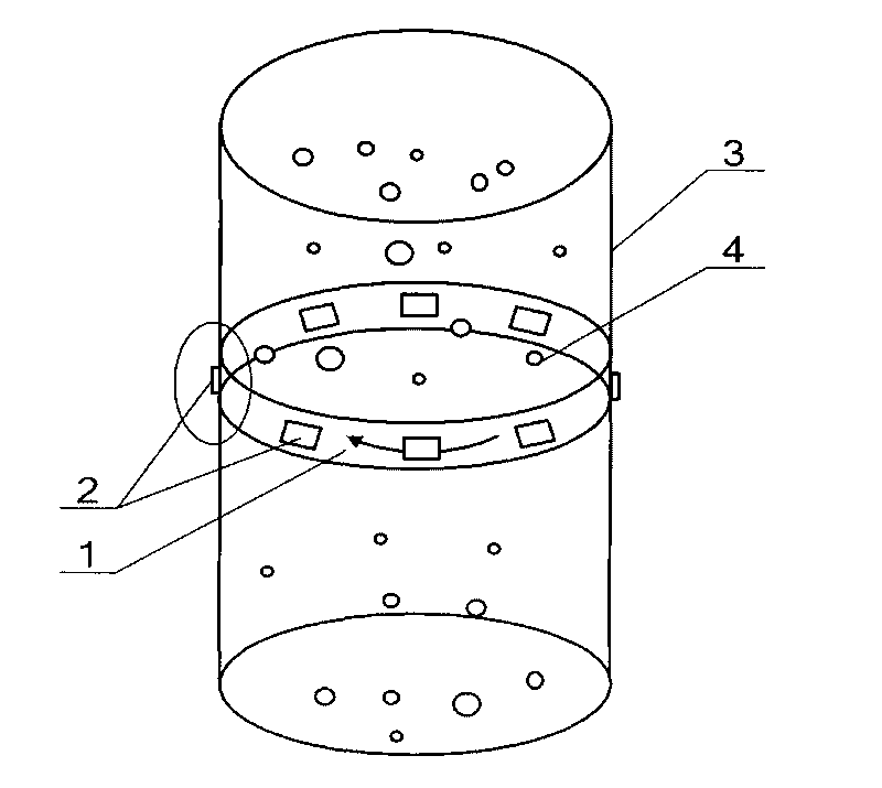
[0027] Such as figure 1 As shown, the device for detecting distribution images of substances in fluid includes a detection ring 1 and eight sensing units 2 .

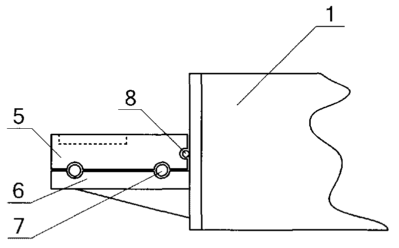
[0028] Such as figure 2 As shown, the detection ring 1 is a transparent cylinder with both ends open, and a bracket 6 and a detection platform 5 are arranged along the circumference of the outer wall of the detection ring 1 . The bracket 6 is circular, and the inner side wall of the bracket 6 is fixedly connected with the outer side wall of the detection ring 1 . The detection platform 5 is circular, and the detection platform 5 is arranged on the support 6 , a bearing 7 is arranged between the detection platform 5 and the support 6 , and a ball 8 is arranged between the inner wall of the detection platform 5 and the outer wall of the detection ring 1 . The detection table 5 is connected with the motor, and the detection table 5 can rotate on the support 6 relative to the detection ring 1 and the support 6 .

[0029...


PUM


Abstract

The invention relates to a device and a method for detecting distribution image of each substance in fluid. The existing device has complex structure and low precision. The invention comprises a detection ring and eight sensing units, wherein, a detection stand on the outer side wall of the detection ring can rotate opposite to the detection ring; eight groups of placing slots are distributed on the upper end surface of the detection stand, and each group contains seven placing slots; each sensing unit comprises seven collimators, the middle collimator is connected with the single port of a Y-shaped shunt, and double ports are respectively connected with a laser and a detector; and three adjacent collimators on two sides are respectively connected with three lasers and three detectors. When being detected, the detection ring is installed on a pipeline to be detected; fluid to be detected flows through the detection ring, and a data acquisition card collects to obtain 32 electrical signals; the detection stand rotates for 45 degrees, then the electrical signals are collected again, and the distribution image is obtained by processing. The invention adopts a rotary scanning method to use fewer fiber optic sensor units to obtain higher image reconstruction resolution by independently designing pixels and planar optical circuit structure.

Description

technical field [0001] The invention belongs to the technical field of tomography, and relates to a device for detecting distribution images of various substances in a fluid and a method for detecting distribution images of various substances in a fluid using the device. Background technique [0002] Tomography (CT) is a method of detecting objects using source-detector scanning or arranging in a fixed structure. The measured projection data is processed by an image reconstruction algorithm related to the physical background of the measurement process, and finally the image The form reflects the technology of the section information of the measured object. [0003] CT technology began with the image reconstruction theory proposed by J.Radon in 1917. In 1963, American physicist Cormack developed an accurate mathematical method for X-ray CT. In 1973, the first X-ray tomography scanner was invented by Dr. G.N.Hounsfield. The physical background is very extensive, such as vario...

Claims


Application Information

Patent Timeline
Patent Type & Authority Applications(China)
IPC IPC(8): G01N21/01G01N21/17
Inventor 阎春生廖延彪赖淑蓉
Owner ZHEJIANG UNIV
Why Eureka
Try Eureka