Correction method of fisheye image distortion on basis of cubic projection

A fisheye image, distortion correction technology, applied in optical components, optics, instruments, etc., can solve problems such as image deformation, and achieve the effect of overcoming geometric deformation and strong realism

Inactive Publication Date: 2010-06-09
HEBEI UNIV OF TECH
View PDF0 Cites 44 Cited by
  • Summary
  • Abstract
  • Description
  • Claims
  • Application Information

AI Technical Summary

Problems solved by technology

[0002] The fisheye lens imaging stereo vision system has a wide range of applications in the visual navigation of micro-robots and the recognition and positioning of short-distance large-field objects. Field stereo vision perception, but also introduces very serious image distortion. The mai...

Method used


Image

  • Correction method of fisheye image distortion on basis of cubic projection
  • Correction method of fisheye image distortion on basis of cubic projection
  • Correction method of fisheye image distortion on basis of cubic projection

Examples


Embodiment Construction

[0016] Step 1: Obtain the imaging model with the fisheye lens, and calibrate the fisheye lens according to the imaging model to obtain the calibration parameters. This step is calibrated according to the specific parameters of the fisheye lens according to the conventional calibration method.

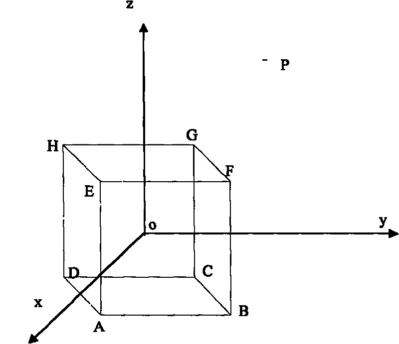
[0017] Step 2: Determine the viewpoint based on the collected fisheye image, and establish a cube perspective projection model with the viewpoint as the origin.

[0018] see figure 1 , first establish the coordinate system, because the cube projection is used, and the cube surface has 6 faces, so the function representing the cube needs to be segmented.

[0019] The center of the cube (that is, the viewpoint of the collected fisheye image) is set as the origin of the observation coordinate system, and a is the side length of the cube.

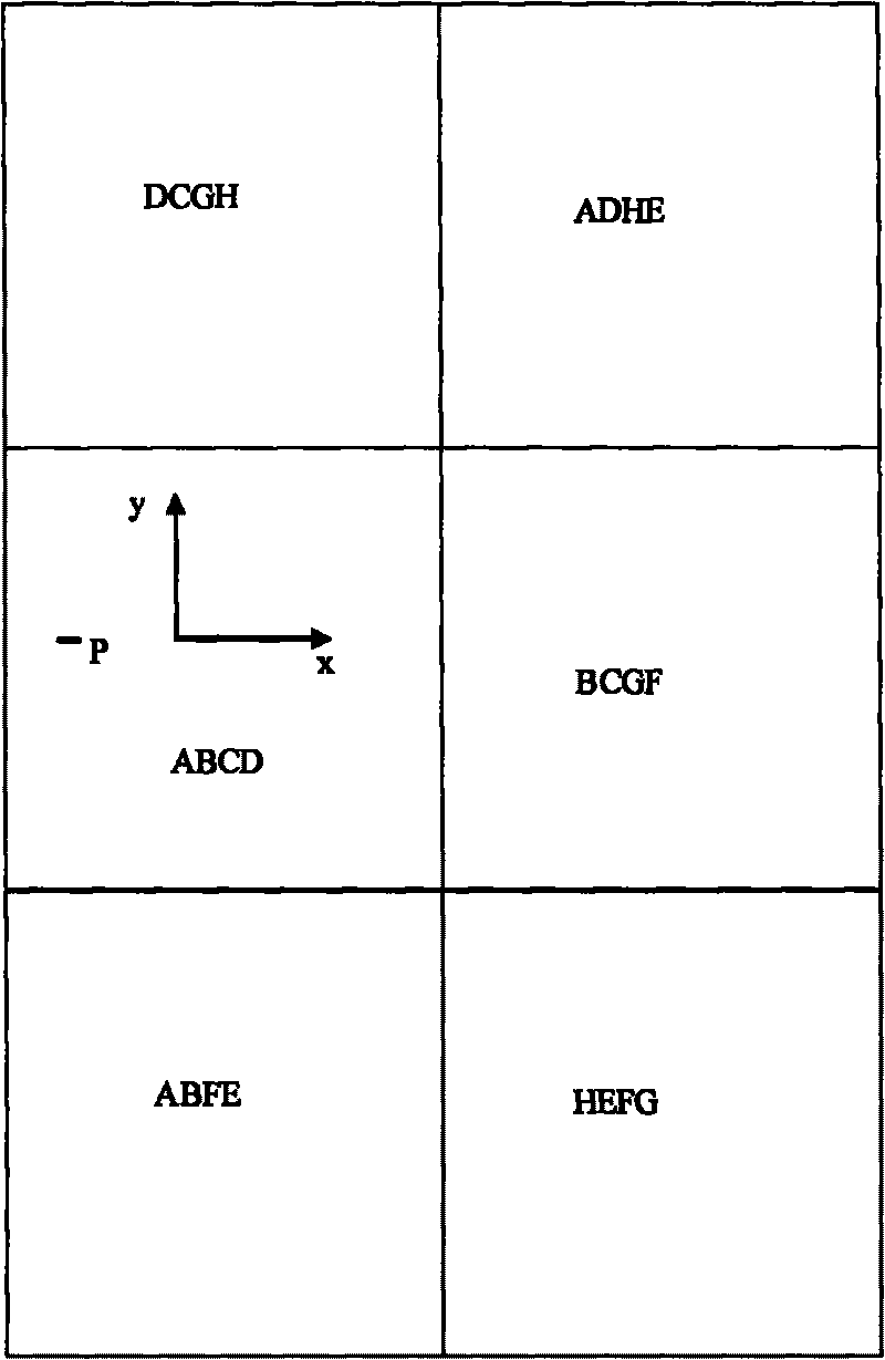
[0020] Then the coordinate equations of the six faces of the cube are:

[0021] ABFE: { x = a ...


PUM


Abstract

The invention belongs to the field of advanced manufacturing technology, relating to a correction method of fisheye image distortion on the basis of cubic projection. The correction method comprises the following steps: 1. using a fisheye lens to obtain an imaging model, and calibrating the fisheye lens according to the imaging model to obtain a calibration parameter; 2. according to the collected fisheye image, determining a viewpoint, taking the viewpoint as the original point of a coordinate system, and building a cubic perspective projection model to obtain the cubic perspective projection of a spatial point; 3. building a mapping relation between the cubic perspective projection of the spatial point and the fisheye image; and 4. using bilinearity interpolation to realize the distortion correction of the fisheye image. The invention utilizes a cubic projection model to correct distorted fisheye images and can effectively overcome the geometric distortion existing in the original fisheye images, and the corrected image conforms to the intuitional feeling of people and has strong sense of reality.

Description

technical field [0001] The invention belongs to the field of advanced manufacturing technology and relates to a fisheye lens image distortion geometric correction method. Background technique [0002] The fisheye lens imaging stereo vision system has a wide range of applications in the visual navigation of micro-robots and the recognition and positioning of short-distance large-field objects. Field stereo vision perception, but also introduces very serious image distortion. The main reason for image distortion is that the real imaging surface of the fisheye lens is not a plane, but a curved surface that is approximately spherical. Therefore, the imaging of the fisheye lens is not an ideal perspective Projection cannot be calibrated by conventional camera calibration methods. This requires the use of a wide-angle or fisheye camera with a large field of view. But the images taken with a wide-angle or fisheye camera have very severe distortion. If we want to take advantage of ...

Claims


Application Information

Patent Timeline
IPC IPC(8): G02B27/00
Inventor 丁承君段萍睢佰龙王南
Owner HEBEI UNIV OF TECH
Why Eureka
Try Eureka