Liquid crystal filling method

A liquid crystal and filling area technology, applied in nonlinear optics, instruments, optics, etc., can solve problems affecting panel uniformity and display quality, sinking of the surrounding area, and bulging of the central area of ​​the second substrate, etc.

Active Publication Date: 2010-06-09
吴江汾湖科技创业服务有限公司
View PDF0 Cites 4 Cited by
  • Summary
  • Abstract
  • Description
  • Claims
  • Application Information

AI Technical Summary

Problems solved by technology

[0004] The purpose of the present invention is to provide a method for filling liquid crystals to solve the problem in the prior art that the surrounding area has a height difference compared with the cen

Method used


Image

  • Liquid crystal filling method
  • Liquid crystal filling method
  • Liquid crystal filling method

Examples


Embodiment Construction

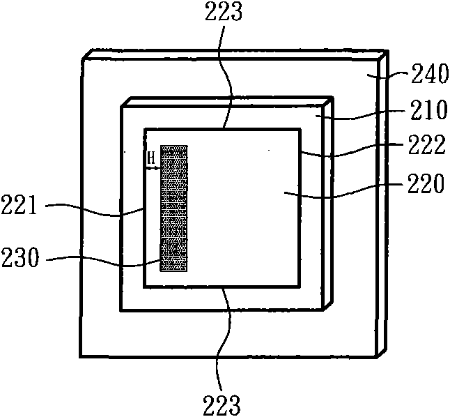
[0022] Please refer to Figure 2a to Figure 2c , which is a schematic diagram of the first embodiment of the liquid crystal filling method of the present invention, the steps are as follows, firstly, a carrying platform 240 is provided. A first substrate 210 is placed on the carrying platform 240, wherein the first substrate 210 has a liquid crystal filling region 220, and the liquid crystal filling region 220 has a first edge 221, a second edge 222 and two sides Side 223. The liquid crystal filling area 220 also has a buffer area A. As shown in FIG. A certain amount of liquid crystal 230 is dropped on the liquid crystal filling area 220 at a position of a buffer interval H from the buffer zone A near the first edge 221 . Such as Figure 2b As shown, the position of the air knife 270 is fixed, and the carrier table 240 carries the first substrate 210 and moves along a first direction D1, and the liquid crystal 230 is moved from the first edge 221 to the second edge by the w...


PUM


Abstract

The invention provides a liquid crystal filling method which comprises the following steps of: providing a bearing table; placing a baseplate with a liquid crystal filling area on the bearing table, wherein the liquid crystal filling area is also provided with a buffer area; dripping liquid crystals into the liquid crystal filling area; and utilizing a wind cutter to enable the liquid crystals of the liquid crystal filling area to diffuse along one direction.

Description

technical field [0001] The invention relates to a method for filling liquid crystals, in particular to a method for filling liquid crystals by using an air knife to diffuse and fill them. Background technique [0002] Please refer to Figure 1a , a schematic diagram of a traditional liquid crystal filling method on a substrate; firstly, a first substrate 110 is provided, and then a certain amount of liquid crystal 130 is dropped and evenly distributed on each position of the first substrate 110 . A second substrate 120 is provided, and a sealant 121 is coated around the second substrate 120 . The area surrounded by the sealant 121 is larger than the above-mentioned positions where the liquid crystals 130 are distributed on the first substrate 110 . After the liquid crystal 130 dropped on the first substrate 110 diffuses for a period of time, the first substrate 110 and the second substrate 120 or panels are assembled. Next, an ultraviolet (UV) light L is applied to the ass...

Claims


Application Information

Patent Timeline
IPC IPC(8): G02F1/1341G02F1/1339G02F1/1333
Inventor 杨俊宏邱献清
Owner 吴江汾湖科技创业服务有限公司
Why Eureka
Try Eureka