Supercharge Your Innovation With Domain-Expert AI Agents!

Liquid crystal display panel

A liquid crystal display panel and liquid crystal layer technology, which is applied to static indicators, optics, instruments, etc., can solve problems such as brightness changes of liquid crystal display panels 1, afterimages of liquid crystal molecules on liquid crystal display panels 1, flickering of display panels 1, etc., and achieve improvement Brightness and color deviation, the effect of improving quality and reliability

Inactive Publication Date: 2013-08-21
INNOLUX CORP
View PDF0 Cites 0 Cited by
  • Summary
  • Abstract
  • Description
  • Claims
  • Application Information

AI Technical Summary

Problems solved by technology

[0006] Continuing from the above, when adjusting the brightness and color of the liquid crystal display panel 1, the voltage of the common electrode 123 is usually set to a fixed voltage, and then the pixel structure 10 at a specific position is used as a judgment reference to adjust the pixel structure 10 The voltage of the pixel electrode 112 in the middle (ie node V P voltage value), so that the liquid crystal molecules are deflected under the influence of the voltage difference between the pixel electrode 112 and the common electrode 123, and then the brightness of the liquid crystal display panel 1 is changed.
[0007] However, when the above method is used, no matter the pixel electrode 112 or the common electrode 123 will have signal attenuation, so that the common voltage V in the pixel structure 10 at different positions com Levels are subject to change
As a result, the brightness and color of each pixel structure 10 in the liquid crystal display panel 1 cannot achieve the desired effect, and the problem of flickering in the liquid crystal display panel 1 is likely to occur. After a long time, the polarization of the liquid crystal molecules will be caused. and the generation of afterimage phenomenon in the liquid crystal display panel 1, which in turn affects the quality and reliability of the liquid crystal display panel 1

Method used


Image

  • Liquid crystal display panel
  • Liquid crystal display panel
  • Liquid crystal display panel

Examples


Embodiment Construction

[0061] The liquid crystal display panel and its pixel structure according to preferred embodiments of the present invention will be described below with reference to related figures.

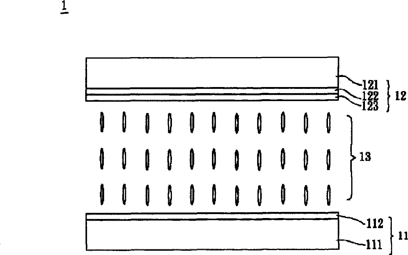
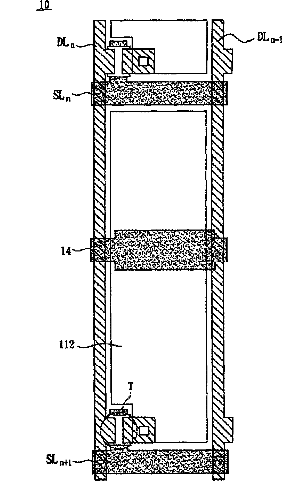
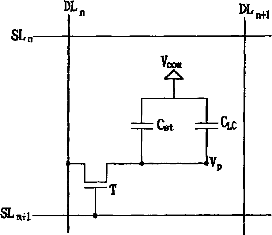
[0062] Please refer to Figure 5 As shown, it is a schematic cross-sectional view of a liquid crystal display panel 2 according to a preferred embodiment of the present invention. The liquid crystal display panel 2 includes a first substrate 21 , a second substrate 22 , a liquid crystal layer 23 and a multi-pixel structure (not shown in the figure). The first substrate 21 is disposed opposite to the second substrate 22 , and the liquid crystal layer 23 is disposed between the first substrate 21 and the second substrate 22 . Wherein, these pixel structures are arranged in a matrix, and each pixel structure is arranged between two adjacent data lines and two adjacent scan lines. In addition, the liquid crystal display panel 2 can be a twisted nematic (TN) type liquid crystal display panel, a mul...


PUM


Abstract

The invention discloses a liquid crystal display panel, which comprises a first substrate, a second substrate, a plurality of pixel structures and a liquid crystal layer, wherein the second substrate and the first substrate are arranged oppositely; each pixel structure comprises a first data line, a second data line, a scanning line, a first electrode and a common electrode pattern; the liquid crystal layer is configured between the first and second substrates; the first and second data lines are actually arranged in parallel; the scanning lines are intercrossed with the first and second datalines; the first electrodes and the common electrode patterns are positioned between the first and second data lines; the first electrodes and the common electrode patterns are arranged oppositely; each first electrode has at least one first pattern and at least one second pattern; the first patterns are electrically connected with the first data lines and the scanning lines respectively; the second patterns are electrically connected with the second data lines and the scanning lines respectively; the first data lines, the second data lines, the scanning lines and the first electrodes are configured on the first substrate; and the common electrode patterns are configured on the second substrate.

Description

technical field [0001] The present invention relates to a display panel and its pixel structure, in particular to a liquid crystal display panel and its pixel structure. Background technique [0002] Liquid crystal display panels are one of the most common display panels at present, and are becoming more and more popular because of their advantages of high resolution, light weight, thin thickness, and low power consumption. Currently common liquid crystal display panels include Twisted Nematic (TN) liquid crystal display panels, Multi-Domain Vertically Aligned (MVA) liquid crystal display panels, In-Plane Switching (IPS) type liquid crystal display panel and fringe-field switching (Fringe-Field Switching, FFS) type liquid crystal display panel, etc. [0003] Please also refer to figure 1 and figure 2 As shown, it is a schematic cross-sectional view of a known twisted nematic (Twisted Nematic, TN) liquid crystal display panel, figure 2 for figure 1 A schematic top view...

Claims


Application Information

Patent Timeline
Patent Type & Authority Patents(China)
IPC IPC(8): G02F1/1362G02F1/133H01L27/12G09G3/36
Inventor 宋立伟周政旭
Owner INNOLUX CORP
Features
  • R&D
  • Intellectual Property
  • Life Sciences
  • Materials
  • Tech Scout
  • Unparalleled Data Quality
  • Higher Quality Content
  • 60% Fewer Hallucinations
Learn More