Clamping and positioning device of K-shaped linear ultrasonic motor based on continuous amplitude transformer principle

A linear ultrasonic motor, clamping and positioning technology, applied in piezoelectric effect/electrostrictive or magnetostrictive motors, generators/motors, electrical components, etc. Guaranteeing the stability of stator motion and other issues

Inactive Publication Date: 2010-06-09
NANJING UNIV OF AERONAUTICS & ASTRONAUTICS
View PDF8 Cites 15 Cited by
  • Summary
  • Abstract
  • Description
  • Claims
  • Application Information

AI Technical Summary

Problems solved by technology

In this kind of clamping device, the slide rail connecting the bottom plate and the clamping part is arranged on the symmetrical line of the stator. Although it ensures that the stator cannot move in the direction of motion of the motor guide rail, it cannot limit the rotation of the stator in three directions. , can not guarantee the stability of the stator movement, thereby reducing the load capacity, and the operating efficiency is not high

Method used


Image

  • Clamping and positioning device of K-shaped linear ultrasonic motor based on continuous amplitude transformer principle
  • Clamping and positioning device of K-shaped linear ultrasonic motor based on continuous amplitude transformer principle
  • Clamping and positioning device of K-shaped linear ultrasonic motor based on continuous amplitude transformer principle

Examples


specific Embodiment approach 1

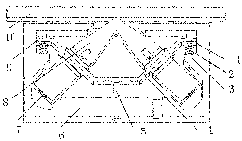
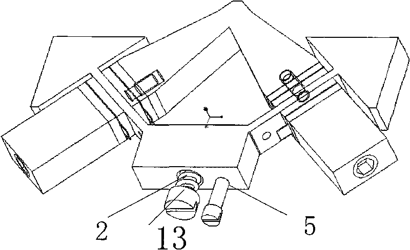
[0016] Specific embodiment 1: A clamping and positioning device for a linear ultrasonic motor such as figure 1 shown. Its characteristics are: 1. The stator and the supporting part 1 are connected by a compression spring 2 and a cylindrical rail 9, and the clamping parts include a cylindrical rail 9, a compression spring 2, and an open rectangular outer frame 6. The cylindrical rail 9 is fixedly connected with the open rectangular outer frame 6 with screws. The compression spring 2 and the cylindrical rail 2 are divided into two left and right sides, and the axial direction is perpendicular to the direction of motion of the guide rail 10 . The arm tail 1 is a transverse rectangular plate, on which there are circular holes equivalent to the diameter of the cylindrical rail. The compression spring 2 is installed on the cylindrical rail 9, and is clamped between the arm tail 1 and the boss 2. The two Langevin vibrators are fixed on the clamping part, so the Langevin vibrators...

specific Embodiment approach 2

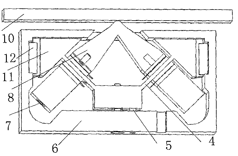
[0018] Specific embodiment 2: A clamping and positioning device for a linear ultrasonic motor such as figure 2 shown. Its characteristics are: 1. The stator and the clamping part are connected by slide rails, and the clamping part includes a slide block 11, a limit slide rail 12 and an open rectangular outer frame 6. Between the limit slide rail 12 and the open rectangular outer frame, between the support arm 4 and the slide block 11, all are fixedly connected with screws. The slide rail is divided into two left and right sides, and its sliding direction is perpendicular to the moving direction of the guide rail 10 . The clamping part fixes the two Langevin vibrators, so the movement of the Langevin vibrators is realized through the slide rail. This device limits the displacement and rotation of the stator in other directions, thereby reducing the useless work of the stator and improving efficiency. 2. The preload can be applied and measured, including the compression bolt...


PUM


Abstract

The invention relates to a clamping and positioning device of a K-shaped linear ultrasonic motor based on the continuous amplitude transformer principle, belonging to the technical field of ultrasonic motors. The clamping and positioning device comprises an opening outline border (6) and a supporter. On one hand, the device ensures that a stator can not move on the motion direction of a motor guide rail and can not rotate on three directions, thus improving the stability of motor structure, ensuring the stability of stator movement and improving load capacity and operation efficiency; and on the other hand, the device can adjust prestress between the stator and a rotor, which is convenient to measure the prestress and ensures that prestress applied in the installation process satisfies design requirements.

Description

Technical field: [0001] The invention relates to a clamping and positioning device for a K-shaped linear ultrasonic motor based on the principle of a continuous horn, and belongs to the technical field of ultrasonic motors. Background technique: [0002] The linear ultrasonic motor is a new type of micro-motor developed and applied rapidly in the 1980s. It uses the inverse piezoelectric effect of the piezoelectric element and the ultrasonic vibration of the elastic body, and through the friction between the stator and the mover, the elastic The micro-vibration of the body is converted into the macroscopic linear (rotational) motion of the mover, which directly pushes the load. It has the advantages of compact structure, high torque at low speed, fast response, high positioning accuracy and electromagnetic compatibility. It has broad application prospects in aerospace, weapon equipment and precision drive fields. [0003] At present, research on linear ultrasonic motors in ...

Claims


Application Information

Patent Timeline
Patent Type & Authority Applications(China)
IPC IPC(8): H02N2/04
Inventor 姚志远王长茹耿冉冉
Owner NANJING UNIV OF AERONAUTICS & ASTRONAUTICS
Why Eureka
Try Eureka