
Time synchronization node and method thereof

A technology of time synchronization and nodes, which is applied in the field of communication, can solve problems such as the inability to achieve minute-to-second time synchronization between relay stations and base stations, and the lack of time synchronization in wireless communication systems, achieving low-cost effects

Inactive Publication Date: 2010-06-09
ZTE CORP
View PDF0 Cites 30 Cited by
  • Summary
  • Abstract
  • Description
  • Claims
  • Application Information

AI Technical Summary

Problems solved by technology

[0006] Aiming at the problem that the existing technology cannot realize the minute-to-second time synchronization between the relay station and the base station when the relay station has GPS and lacks the time synchronization of the wireless communication system when the relay station does not have GPS, the present invention aims to provide a Time synchronization nodes and methods to solve the above problems

Method used


Image

  • Time synchronization node and method thereof
  • Time synchronization node and method thereof
  • Time synchronization node and method thereof

Examples


Embodiment 1

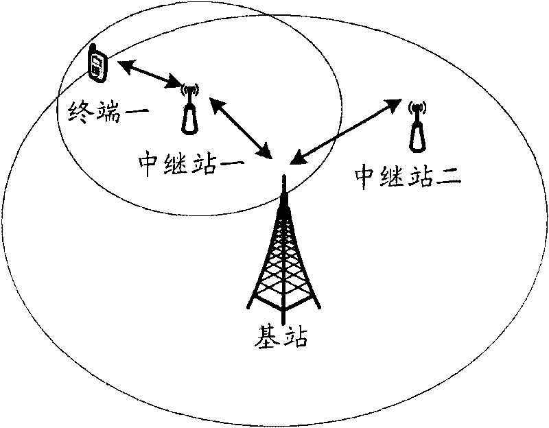
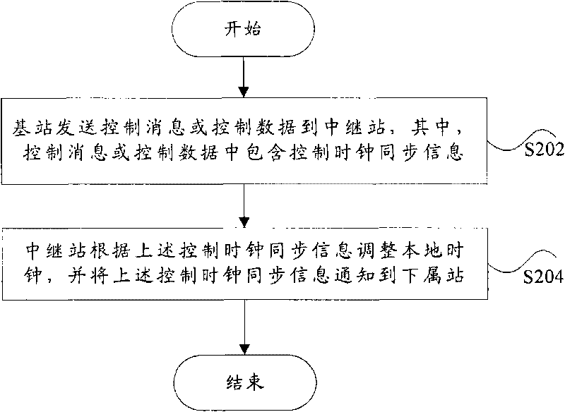
[0022] based on figure 1 In the system shown, the upstream node is a base station, and the downstream node is a relay station without GPS (for example, figure 1 In the case of relay station 1 and relay station 2), such as figure 2 As shown, it is the flow process of this embodiment, including:

[0023] Step S202, the base station sends a control message or control data to the relay station, wherein the control message or control data includes control clock synchronization information.

[0024] Step S204, the relay station adjusts the local clock according to the control clock synchronization information, and notifies the control clock synchronization information to its subordinate stations. Wherein, the subordinate station may be a terminal or other relay stations. Other relay stations or terminals adjust their local clocks respectively according to the received control messages or control data to achieve time synchronization.

[0025] In the specific implementation proce...

Embodiment 2

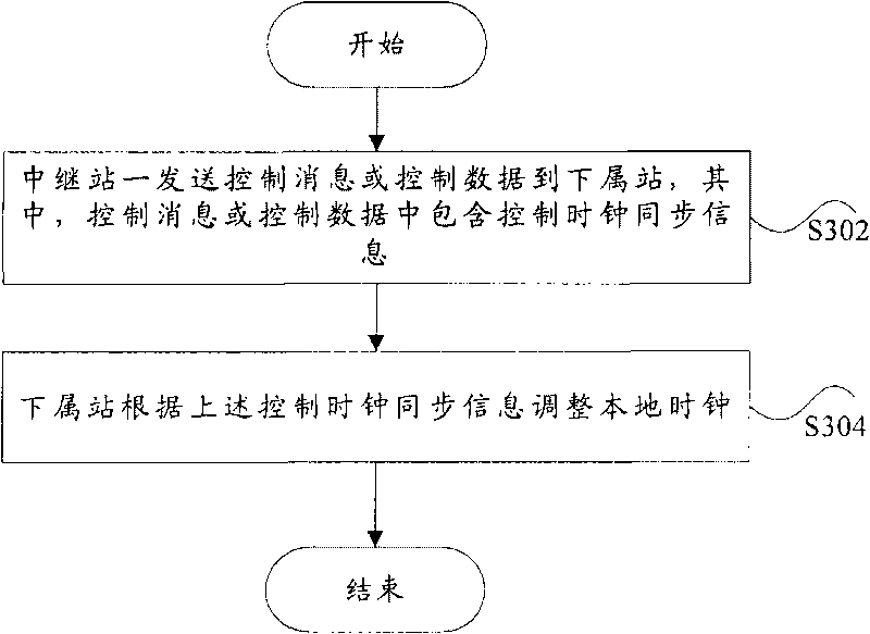
[0044] based on figure 1 In the system shown, when the above-mentioned upstream node is a relay station (relay station 1) with GPS, and the above-mentioned downstream node is a relay station (relay station 2) or a terminal without GPS, the base station and relay station 1 use the synchronization signal ( For example, CLK-SYN message) to achieve time synchronization, but the time synchronization between relay station 1 and its subordinate stations (relay station 2 or terminal 1) is realized through the control message or control data sent by relay station 1. Such as image 3 As shown, it is the flow process of this embodiment, including:

[0045] In step S302, the first relay station sends a control message or control data to a subordinate station, wherein the control message or control data includes control clock synchronization information.

[0046] Step S304, the subordinate station adjusts the local clock according to the above control clock synchronization information. ...


PUM


Abstract

The invention provides a time synchronization node and a method thereof. The time synchronization method comprises: a downstream node receives a control message or control data transmitted by an upstream node periodically or non-periodically, wherein the control message or control data comprises control clock synchronization information; the downstream node adjusts the local clock according to the control clock synchronization information. By adopting the invention, a control message or control data which includes the control clock synchronization information can be transmitted to a subordinate station via a relay station under a condition that the minute-second time synchronization among a base station, a relay station and a terminal is realized with a high efficient and low cost or the relay station has time service equipment, so as to realize the time synchronization among the base station, the relay station and the terminal and make up a gap of the prior art.

Description

technical field [0001] The present invention relates to the communication field, in particular to a time synchronization node and method. Background technique [0002] Currently, wireless communication systems use electromagnetic waves to communicate with fixed or mobile wireless communication terminals (such as mobile wireless phones or notebook computers with wireless communication cards, referred to as terminals). The electromagnetic wave frequency assigned by the wireless communication system to wireless devices is divided into multiple carrier frequencies as wireless communication channels, and the wireless channels designated by the base station are used to provide wireless coverage within a certain geographical range. This geographical range is called a cell. Generally, terminals are located in the wireless system within coverage. Theoretically the base station should be in the center of the cell. [0003] In order to expand the system coverage or expand the system ...

Claims


Application Information

Patent Timeline
Patent Type & Authority Applications(China)
IPC IPC(8): H04B7/26
Inventor 刘扬幸国全
Owner ZTE CORP
Learn More