
Resource scheduling method and system, base station and terminal therefor

A resource scheduling and terminal technology, applied in the communication field, can solve the problems of fair and effective allocation of resources for uplink real-time services, achieve the effects of fair and effective allocation of resources, reduction of data packet loss, and improvement of user experience

Inactive Publication Date: 2010-06-09
ZTE CORP
View PDF4 Cites 25 Cited by
  • Summary
  • Abstract
  • Description
  • Claims
  • Application Information

AI Technical Summary

Problems solved by technology

[0006] Considering the problem that the base station in the related art cannot allocate resources fairly and effectively for uplink real-time services, the present invention is made. Therefore, the main purpose of the present invention is to provide a resource scheduling method and system, a base station, and a terminal to Solving the above-mentioned problems in related technologies

Method used


Image

  • Resource scheduling method and system, base station and terminal therefor
  • Resource scheduling method and system, base station and terminal therefor
  • Resource scheduling method and system, base station and terminal therefor

Examples


Embodiment 1

[0095] According to an embodiment of the present invention, a base station is provided.

[0096] Figure 4 shows the structure of the base station according to Embodiment 1 of the device of the present invention, Figure 5 The structure of the base station according to the preferred embodiment of the present invention is shown. like Figure 4 As shown, the base station according to Embodiment 1 of the apparatus of the present invention includes: a first receiving unit 2 , a first determining unit 4 , and a scheduling unit 6 . The functions of the above modules are described in detail below.

[0097] (1) The first receiving unit 2

[0098] The first receiving unit 2 is configured to receive bandwidth request messages from multiple terminals requesting real-time services, wherein the bandwidth request messages carry real-time service data queuing delay information in the data queue of the corresponding terminal, preferably, the The queuing delay information may be a queuing...

Embodiment 2

[0107] According to an embodiment of the present invention, a terminal is provided.

[0108] Image 6 shows the structure of the terminal according to the second embodiment of the device of the present invention, Figure 7 The structure of the terminal according to the preferred embodiment of the present invention is shown.

[0109] like Image 6 As shown, the terminal according to the second embodiment of the device of the present invention includes: a second receiving unit 1 , a second determining unit 3 , and a sending unit 5 . The functions of the above modules are described in detail below.

[0110] (1) The second receiving unit 1

[0111] The second receiving unit 1 is used for receiving data from the upper layer.

[0112] (2) The second receiving unit 3

[0113] The second receiving unit 3 is connected to the second receiving unit 1 and configured to determine the queuing delay information of the data received by the second receiving unit 1 .

[0114] Preferably,...


PUM


Abstract

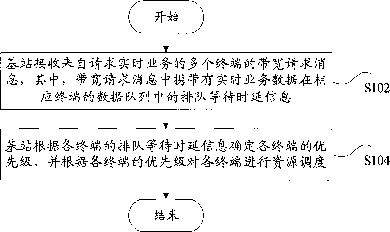
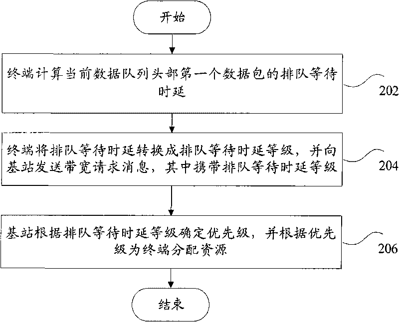
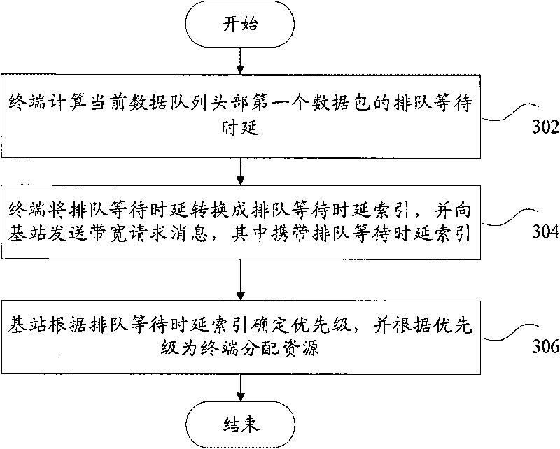
The invention discloses a resource scheduling method and system, a base station and terminals therefor. The resource scheduling method comprises the following steps: the base station receives a bandwidth request message from a plurality of terminals of the request real-time service, wherein the bandwidth request message carries queuing time delay information of real-time service data in the data queue of the corresponding terminal; and the base station determines the priority of the terminals according to the queuing time delay information of the terminals and carries out the resource scheduling on the terminals according to the priority of the terminals. By introducing the data queuing time delay factor in the process of uplink real-time service resource distribution, compared with the prior art, the base station can distribute resources to the terminals with large data queuing time delay in time to reduce the phenomenon of dropped-out data, thereby fairly and effectively distributing resources to the terminals and enhancing the user experience.

Description

technical field [0001] The present invention relates to the communication field, and in particular, relates to a resource scheduling method and system, a base station, and a terminal. Background technique [0002] In a wireless communication system, a base station is a device that provides services for terminals. The base station communicates with the terminal through the up / down link. The downlink (or forward) is the direction from the base station to the terminal, and the uplink (or reverse) is the direction from the terminal to the base station. The base station transmits data, and can also simultaneously receive data from the base station through the downlink. [0003] In a data transmission system using base station scheduling control, usually the base station performs scheduling and allocation of system resources. For example, the base station performs resource allocation during downlink transmission, allocates resources required for uplink transmission to the termin...

Claims


Application Information

Patent Timeline
Patent Type & Authority Applications(China)
IPC IPC(8): H04W72/04H04L12/56
Inventor 夏薇鲁照华关艳峰刘颖朱登魁
Owner ZTE CORP
Learn More