Multi-interface communication device, terminal, and path switching method

a communication device and interface technology, applied in the field of multi-interface communication, can solve the problems of unfavorable device use, unfavorable external terminal device, and unfavorable device use, so as to reduce time loss, reduce packet loss in switching, and efficiently utilize network resources

Inactive Publication Date: 2011-02-22
PANASONIC CORP
View PDF16 Cites 18 Cited by
  • Summary
  • Abstract
  • Description
  • Claims
  • Application Information

AI Technical Summary

Benefits of technology

[0019]An object of the present invention is to reduce packet loss due to communication interruption as a result that a master router is switched from a switching-origin router to a switching-destination router rapidly when the switching-origin router as the master router malfunctions in a wireless network, to utilize the network resources efficiently.

Problems solved by technology

Equipping such plural wireless access interfaces on a terminal device undesirably increases its cost and size, which is particularly problematic when plural terminal devices are carried.
This disables the terminal device to communicate because regular RA messages remain transmitted even when connection of the router to an external network is overloaded, or difficult or impossible due to decreased radio signal strength when connected through a wireless access interface.
In order for the terminal device to switch the default router to another, the terminal device needs to recognize that communication with an external terminal device has been disabled, which requires a long time.
Accordingly, when communication of the router with an external network is disabled because of a reason other than a shutdown, the communication is undesirably interrupted over a long time.
That is, in order for the backup router to be switched to the master rapidly, the backup router starts establishing connection with the external network when the connection state of the master router becomes unstable.
However, in the method disclosed in WO 2004 / 093397, a node on the LAN waits for updating the routing table until the executable time described in the routing possible message elapses although the switching-destination router has actually completed connection with the external network, thus disabling rapid router switching.
Meanwhile, the node updates the routing table when the executable time elapses although connection with the external network has not completed actually, thus failing to receive packets.
Further, in a LAN employing a connection oriented protocol such as Bluetooth (registered trademark), a node on the LAN cannot receive a routing possible message transmitted by the switching-destination router if the node has not established Layer 2 connection for transmitting IP packets with the switching-destination router, thus disabling normal router switching.
Even if a node during communication searches for a default router autonomously to attempt switching after receiving a routing stop message from the switching-origin router, link connection with the switching-destination router has not been established, and thus the routing table cannot be updated.

Method used


Image

  • Multi-interface communication device, terminal, and path switching method
  • Multi-interface communication device, terminal, and path switching method
  • Multi-interface communication device, terminal, and path switching method

Examples


first exemplary embodiment

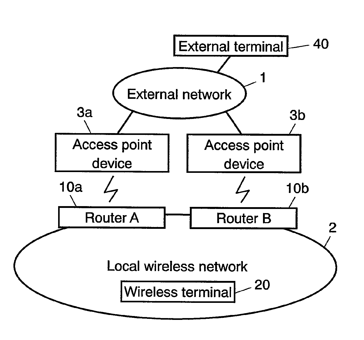
[0130]FIG. 3 illustrates the makeup of a communication system according to the present invention, where routers 10a, 10b and wireless terminal 20 communicate with each other wirelessly to compose local wireless network 2. External network 1 such as the Internet has access point devices 3a, 3b and external terminal 40 connected thereto. Routers 10a, 10b connect to access point devices 3a, 3b through an access line by wireless communication.

[0131]In the communication system with the above-described makeup, wireless terminal 20 communicates with external terminal 40 through router 10a. After that, router 10a detects that the communication link can possibly be disconnected due to a deteriorated state of communication between router 10a and access point device 3a. Router 10a solicits another router 10b on local wireless network 2 for takeover of the communication related to wireless terminal 20. Router 10b, responding to the solicitation, establishes a communication link with access poin...

second exemplary embodiment

[0317]A description is made for the second exemplary embodiment of the present invention using the related drawings.

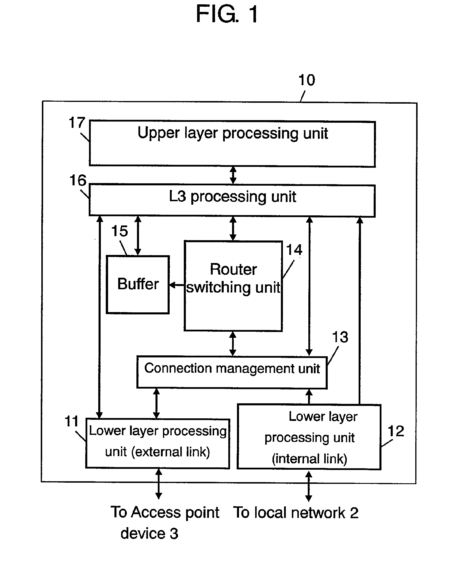
[0318]FIG. 20 illustrates the makeup of a communication system according to the embodiment, which is different from that of the first exemplary embodiment in including multi-interface communication terminal 30 having a communication flow with external terminal 40, instead of switching-origin router A(10a) and wireless terminal 20. This multi-interface communication terminal 30 is different from a router in not including a relay function, where its makeup is the same as that shown in FIG. 1.

[0319]Firstly, a description is made for the operation of multi-interface communication terminal 30 and router B(10b), only about the differences from the first exemplary embodiment.

[0320]First, router switching unit 14 of multi-interface communication terminal 30, when detecting a deteriorated state of the communication with access point device 3a, transmits connection instruction m...


PUM


Abstract

A router, if judging that a routing function is impossible to execute, sends out a connection instruction message including the address of a terminal on a local network terminating the relaying flow, to another router to solicit switching. The router having received the connection instruction message starts a process for connecting with an external network while executing a process for link connection with a terminal, and then sends out a connection completion notice message when the connection with both the external network and the terminal is established. This process enables the router to switch a path rapidly.

Description

[0001]This Application is a U.S. National Phase Application of PCT International Application PCT / JP2005 / 020269.TECHNICAL FIELD[0002]The present invention relates to a multi-interface communication device having plural communication interfaces and to a path switching method in which plural multi-interface devices are switched, particularly to a path switching method in which two or more routers that are multi-interface devices are switched.BACKGROUND ART[0003]Conventionally, a terminal device for mobile communication has been implemented by adding a wireless access interface to a mobile terminal.[0004]However, a wireless access network connected by a wireless access interface has different coverage, bandwidth, communication charge, and the like, depending on its type. Accordingly, to continue communication wherever the terminal device moves, the terminal has been required that has plural interfaces to handle plural wireless access networks with different coverage. Equipping such plur...

Claims


Application Information

Patent Timeline
Patent Type & Authority Patents(United States)
IPC IPC(8): H04W4/00H04W24/04H04W76/04H04W80/04H04W84/12H04W88/14
CPCH04L45/00H04L45/28H04L45/60
Inventor IKEDA, SHINKICHIKUMAZAWA, MASAYUKIFUNABIKI, MAKOTO
Owner PANASONIC CORP
Why Eureka
Try Eureka